Home Products OLED Module Graphic OLED Display WEO016080A

1.54 inch 160x80 SSD1320 OLED Display Module

Model No. WEO016080A

►Type: Graphic
►Structure: COG
►Size: 1.54 inch
►160x80 OLED
►IC:SSD1320
►3V Power supply
►1/80 duty
►Interface: 6800, 8080, SPI, I2C
►Display Color: White
►Support Grayscale

Description

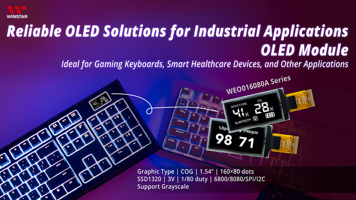
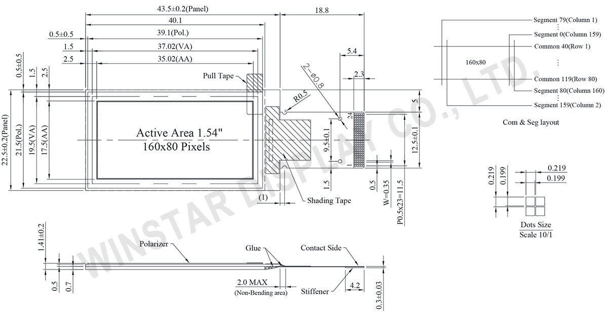
The WEO016080A is a 1.54-inch COG graphic OLED display featuring a resolution of 160x80 dots. It measures 43.5 x 22.5 mm with an active area of 35.02 x 17.50 mm, and its slim profile of 1.41 mm is attributed to its COG structure.

Equipped with the SSD1320 IC, this module supports 6800/8080 8-bit, 4-wire SPI, and I2C interfaces. It offers 4-bit (16 Levels) grayscale and achieves an impressive contrast ratio of 10,000:1.

Operable with a logic power supply voltage ranging from 1.65V to 3.3V (typically 3.0V), the module operates reliably in temperatures from -40°C to +80°C, with a storage capability from -40°C to +85°C.

Ideal for a variety of applications including Networking Products, USB Testers, Smart Watches, Gaming Keyboards, and Smart Healthcare Devices such as oximeters and skin analyzers, the WEO016080A enhances display quality with its crisp and vibrant screen.

With its high resolution (160x80 pixels) and low power consumption, this OLED display module is perfectly suited for performance-driven and efficient applications.


Reliable OLED Solutions for Industrial Applications OLED Module - Ideal for Gaming Keyboards, Smart Healthcare Devices, and Other Applications

DRAWING

1.54 inch 160x80 SSD1320 OLED Display Module - WEO016080A

Data source ref:WEO016080AWPP3N00000

SPECIFICATIONS

Mechanical Data

Item Dimension Unit
Dot Matrix 160 x 80 Dots
Module dimension 43.5 x 22.5 x 1.41 mm
Active Area 35.02 x 17.50 mm
Pixel Size 0.199 x 0.199 mm
Pixel Pitch 0.219 x 0.219 mm
Display Mode Passive Matrix
Display Color Monochrome
Drive Duty 1/80 Duty
Gray Scale 4 bits
Interface 6800,8080,4-Wire SPI,I2C
IC SSD1320
Size 1.54 inch

Absolute Maximum Ratings

Parameter Symbol Min Typ. Max Unit
Supply Voltage for Logic VDD -0.3 4 V
Supply Voltage for Display VCC 0 19 V
Operating Temperature TOP -40 +80 °C
Storage Temperature TSTG -40 +85 °C

Electronical Characteristics

DC Electrical Characteristics

Item Symbol Condition Min Typ Max Unit
Supply Voltage for Logic VDD 1.65 3.0 3.3 V
Supply Voltage for Display VCC 8.0 15.0 15.5 V
High Level Input VIH 0.8×VDD VDD V
Low Level Input VIL 0 0.2×VDD V
High Level Output VOH 0.9×VDD VDD V
Low Level Output VOL 0 0.1×VDD V
VCC Supply Current ICC VDD=3V,VCC=15V
Display 50% Pixel ON
14 21 mA

Interface Pin Function

No. Symbol Function
1 N.C.
(GND)
Reserved Pin (Supporting Pin)
The supporting pin can reduce the influences from stresses on the function pins.
This pin could be connected to external ground as the ESD protection circuit.
2 VCC Power Supply for OEL Panel
This is the most positive voltage supply pin of the chip. It must be connected to external source.
3~4 N.C. Reserved Pin
The N.C. pin between function pins are reserved for compatible and flexible design.
5 BS1 Communicating Protocol Select
These pins are MCU interface selection input. See the following table:
  BS1 BS2
I2C 1 0
4-wire SPI 0 0
8-bit 68XX Parallel 0 1
8-bit 80XX Parallel 1 1
6 BS2
7 VSS Ground of Logic Circuit
This is a ground pin. It also acts as a reference for the logic pins. It must be connected to external ground.
8 IREF Current Reference for Brightness Adjustment
This pin is segment current reference pin. A resistor should be connected between this pin and VSS. Set the current at 10μA maximum.
9 CS# Chip Select
This pin is the chip select input. The chip is enabled for MCU communication only when CS# is pulled low.
10 RES# Power Reset for Controller and Driver
This pin is reset signal input. When the pin is low, initialization of the chip is executed. Keep this pin pull high during normal operation.
11 D/C# Data/Command Control
This pin is Data/Command control pin. When the pin is pulled high, the input at
D7~D0 is treated as display data. When the pin is pulled low, the input at
D7~D0 will be transferred to the command register.
In I2C mode, this pin acts as SA0 for slave address selection.
12 R/W# Read/Write Select or Write
This pin is MCU interface input.
When interfacing to a 68XX-series microprocessor, this pin will be used as
Read/Write (R/W#) selection input. Pull this pin to “High” for read mode and pull it to “Low” for write mode.
When 80XX interface mode is selected, this pin will be the Write (WR#) input.
Data write operation is initiated when this pin is pulled low and the CS# is pulled low.
When serial mode is selected, this pin must be connected to VSS.
13 E/RD# Read/Write Enable or Read
This pin is MCU interface input.
When interfacing to a 68XX-series microprocessor, this pin will be used as the
Enable (E) signal. Read/write operation is initiated when this pin is pulled high and the CS# is pulled low.
When connecting to an 80XX-microprocessor, this pin receives the Read (RD#) signal. Data read operation is initiated when this pin is pulled low and CS# is pulled low.
When serial mode is selected, this pin must be connected to VSS.
14 D0 Host Data Input/Output Bus
These pins are bi-directional data bus connecting to the MCU data bus.
Unused pins are recommended to tie LOW.
When serial interface mode is selected, D2, D1 should be tied together as the serial data input: SDIN, and D0 will be the serial clock input: SCLK.
When I2C mode is selected, D2, D1 should be tied together and serve as SDAout,
SDAin in application and D0 is the serial clock input, SCL.
15 D1
16 D2
17 D3
18 D4
19 D5
20 D6
21 D7
22 VDD Power Supply for Logic
This is a voltage supply pin. It must be connected to external source.
23 VCOMH Voltage Output High Level for COM Signal
This pin is the input pin for the voltage output high level for COM signals. A tantalum capacitor should be connected between this pin and VSS.
24 VCC Power Supply for OEL Panel
This is the most positive voltage supply pin of the chip. It must be connected to external source.

Related Products

go top
close

We value your privacy

By clicking "Allow All Cookies", you agree to the storing of cookies on your device to enhance site navigation, analyse site usage, and assist in our marketing and performance efforts. You can find further information this subject in our policy.

We value your privacy

Winstar and certain third parties use cookies on www.winstar.com.tw. The details regarding the types of
cookies, their purpose and the third parties involved are described below and in our Cookie Policy.
Please click on “Allow All” to consent to our usage of cookies in order to have the best possible
experience on our websites. You can also set your preferences or reject cookies (except for strictly
necessary cookies).

Manage Consent Preferences

Always Active
Essential Cookies

These cookies are essential in order to enable you to move around the website and use its
features, such as setting your privacy preferences, logging in or filling in forms.

Analytics Cookies

Also known as “statistics cookies,” these cookies collect information about how you use a website, like which pages you visited and which links you clicked on. See Detail