Home Productos Pantalla OLED Pantalla OLED Gráfico WEO016080A

Módulo de pantalla OLED SSD1320 de 1.54 pulgadas 160x80

Modelo Nº WEO016080A

►Tipo : Gráfico
►Estructura : COG
►Tamaño : 1.54 pulgada
►Matriz de puntos 160x80
►IC:SSD1320
►Fuente de alimentación de 3V
►1/80 duty
►Interfaz : 6800, 8080, SPI, I2C
►Color de la pantalla: Blanco
►Compatibilidad con escala de grises

Descripción

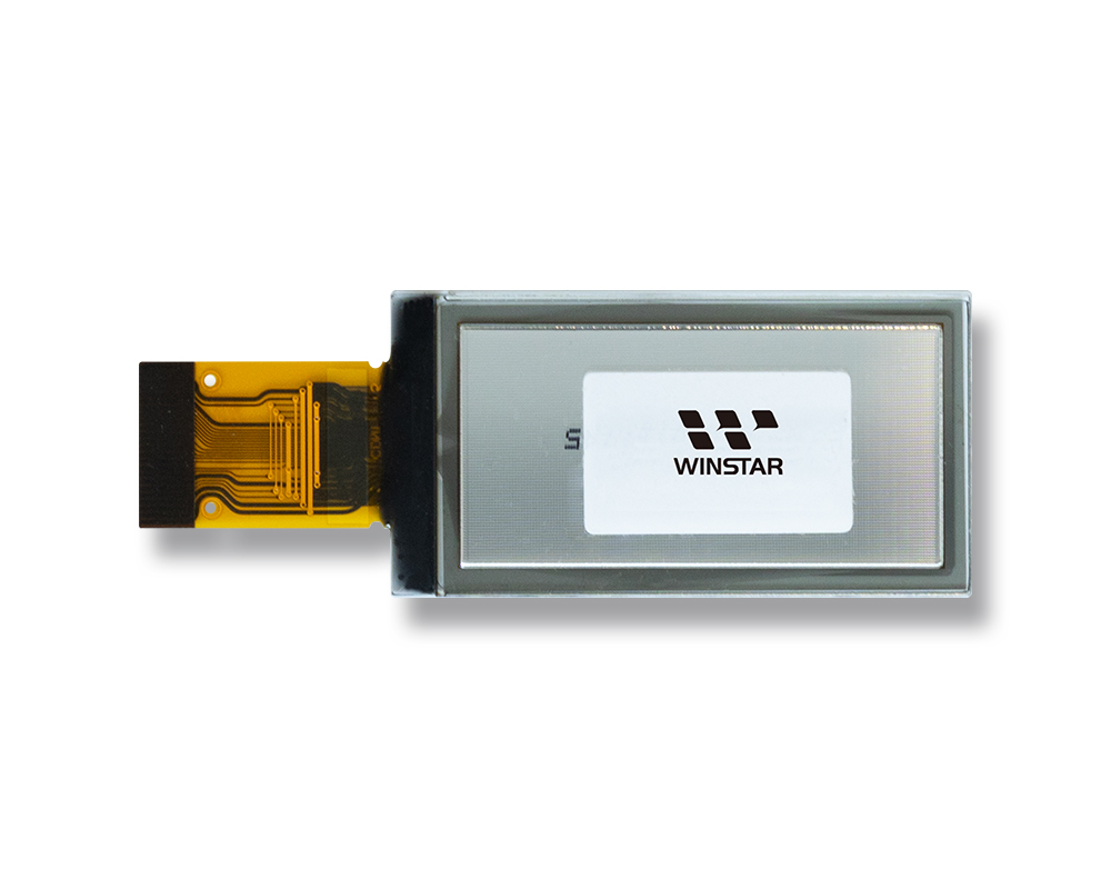
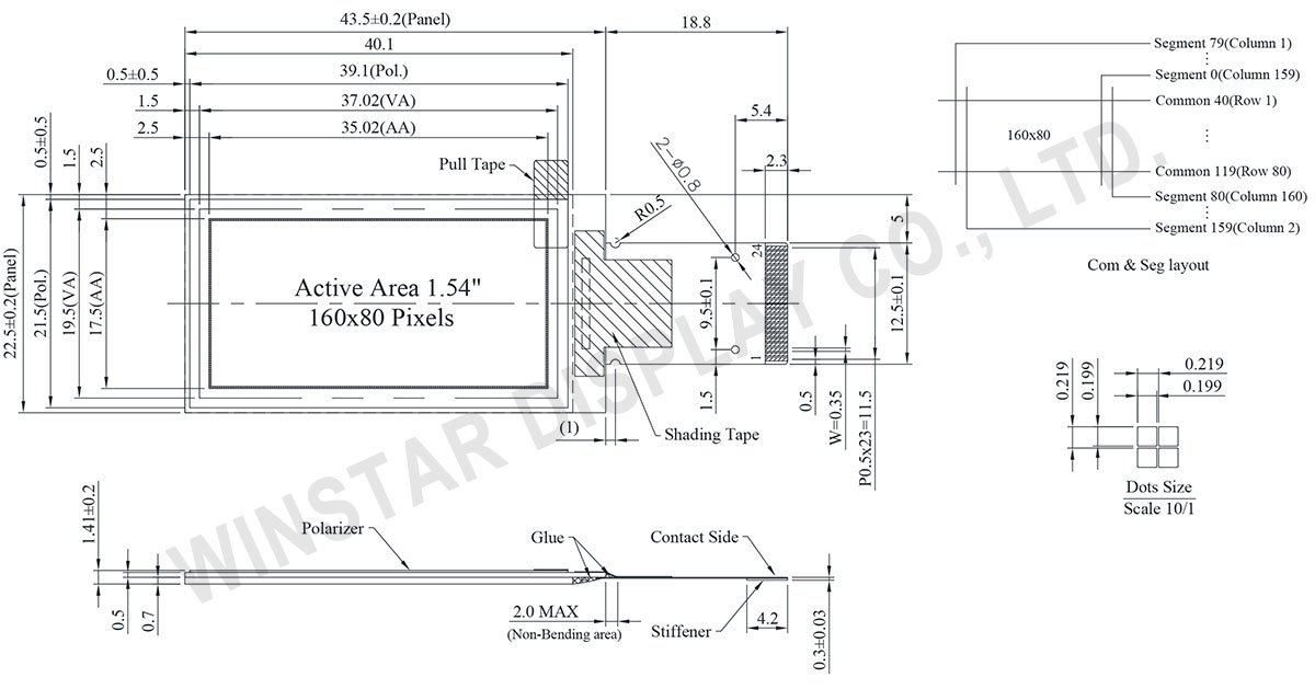
El WEO016080A es un display OLED gráfico COG de 1.54 pulgadas con una resolución de 160x80 puntos. Tiene unas dimensiones de 43.5 x 22.5 mm y un área activa de 35.02 x 17.50 mm, con un perfil delgado de 1.41 mm gracias a su estructura COG.

Equipado con el IC SSD1320, este módulo soporta interfaces 6800/8080 de 4 bits, SPI de 4 cables y I2C. Ofrece una escala de grises de 4 bits (16 niveles) y alcanza una impresionante relación de contraste de 10000:1.

Operando con un rango de voltaje de suministro lógico de 1.65V a 3.3V (típicamente 3.0V), el módulo funciona de manera confiable en temperaturas que van desde -40°C hasta +80°C, con una capacidad de almacenamiento de -40°C a +85°C.

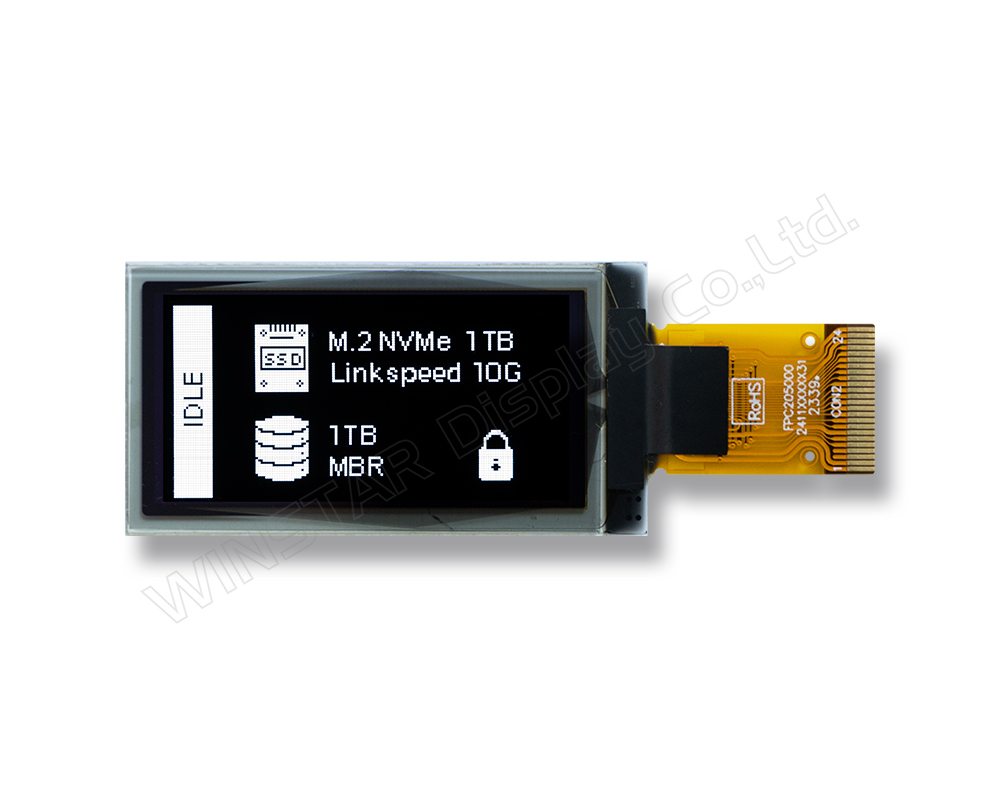
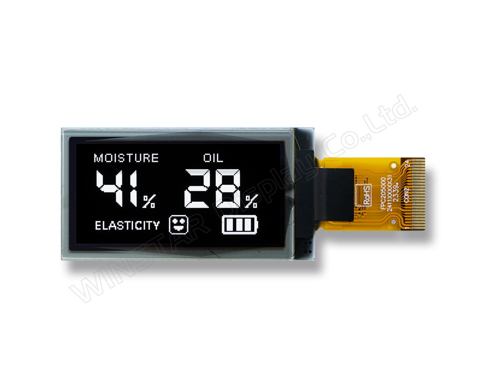
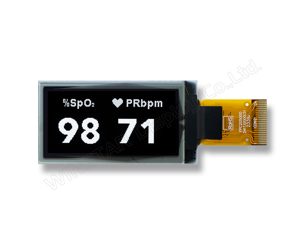
Ideal para una variedad de aplicaciones que incluyen productos de redes, probadores USB, relojes inteligentes, teclados para juegos y dispositivos de salud inteligentes como oxímetros y analizadores de piel, el WEO016080A mejora la calidad de visualización con su pantalla nítida y vibrante.

Con su alta resolución (160x80 píxeles) y bajo consumo de energía, este módulo de display OLED es perfectamente adecuado para aplicaciones orientadas al rendimiento y eficiencia.


Módulo de pantalla OLED SSD1320 de 1.54 pulgadas 160x80 - WEO016080A

DIBUJO

1.54 inch 160x80 SSD1320 OLED Display Module - WEO016080A

Data source ref:WEO016080AWPP3N00000

ESPECIFICACIONES

Datos mecánicos

Elemento Dimensión Unidad
Matriz de puntos 160 x 80 puntos
Dimensión del módulo 43.5 x 22.5 x 1.41 mm
zona activa 35.02 x 17.50 mm
Tamaño del punto 0.199 x 0.199 mm
Distancia entre puntos 0.219 x 0.219 mm
Modo de visualización Matriz pasiva
Color de la pantalla Monocromos
Drive Duty 1/80 Duty
Escala de grises 4 bits
Interfaz 6800,8080,4-Wire SPI,I2C
IC SSD1320
Tamaño 1.54 pulgada

Valores nominales máximos absolutos

Parameter Símbolo Valor mín. Valor típico Valor máx. Unidad
Supply Voltage for Logic VDD -0.3 4 V
Supply Voltage for Display VCC 0 19 V
Temperatura de funcionamiento TOP -40 +80 °C
Temperatura de almacenamiento TSTG -40 +85 °C

Características electrónicas

DC Características electrónicas

Elemento Símbolo Condición Valor mín. Valor típico Valor máx. Unidad
Supply Voltage for Logic VDD 1.65 3.0 3.3 V
Supply Voltage for Display VCC 8.0 15.0 15.5 V
High Level Input VIH 0.8×VDD VDD V
Low Level Input VIL 0 0.2×VDD V
High Level Output VOH 0.9×VDD VDD V
Low Level Output VOL 0 0.1×VDD V
VCC Supply Current ICC VDD=3V,VCC=15V
Display 50% Pixel ON
14 21 mA

Función interfaz Pin

No. Símbolo Función
1 N.C.
(GND)
Reserved Pin (Supporting Pin)
The supporting pin can reduce the influences from stresses on the function pins.
This pin could be connected to external ground as the ESD protection circuit.
2 VCC Power Supply for OEL Panel
This is the most positive voltage supply pin of the chip. It must be connected to external source.
3~4 N.C. Reserved Pin
The N.C. pin between function pins are reserved for compatible and flexible design.
5 BS1 Communicating Protocol Select
These pins are MCU interface selection input. See the following table:
  BS1 BS2
I2C 1 0
4-wire SPI 0 0
8-bit 68XX Parallel 0 1
8-bit 80XX Parallel 1 1
6 BS2
7 VSS Ground of Logic Circuit
This is a ground pin. It also acts as a reference for the logic pins. It must be connected to external ground.
8 IREF Current Reference for Brightness Adjustment
This pin is segment current reference pin. A resistor should be connected between this pin and VSS. Set the current at 10μA maximum.
9 CS# Chip Select
This pin is the chip select input. The chip is enabled for MCU communication only when CS# is pulled low.
10 RES# Power Reset for Controller and Driver
This pin is reset signal input. When the pin is low, initialization of the chip is executed. Keep this pin pull high during normal operation.
11 D/C# Data/Command Control
This pin is Data/Command control pin. When the pin is pulled high, the input at
D7~D0 is treated as display data. When the pin is pulled low, the input at
D7~D0 will be transferred to the command register.
In I2C mode, this pin acts as SA0 for slave address selection.
12 R/W# Read/Write Select or Write
This pin is MCU interface input.
When interfacing to a 68XX-series microprocessor, this pin will be used as
Read/Write (R/W#) selection input. Pull this pin to “High” for read mode and pull it to “Low” for write mode.
When 80XX interface mode is selected, this pin will be the Write (WR#) input.
Data write operation is initiated when this pin is pulled low and the CS# is pulled low.
When serial mode is selected, this pin must be connected to VSS.
13 E/RD# Read/Write Enable or Read
This pin is MCU interface input.
When interfacing to a 68XX-series microprocessor, this pin will be used as the
Enable (E) signal. Read/write operation is initiated when this pin is pulled high and the CS# is pulled low.
When connecting to an 80XX-microprocessor, this pin receives the Read (RD#) signal. Data read operation is initiated when this pin is pulled low and CS# is pulled low.
When serial mode is selected, this pin must be connected to VSS.
14 D0 Host Data Input/Output Bus
These pins are bi-directional data bus connecting to the MCU data bus.
Unused pins are recommended to tie LOW.
When serial interface mode is selected, D2, D1 should be tied together as the serial data input: SDIN, and D0 will be the serial clock input: SCLK.
When I2C mode is selected, D2, D1 should be tied together and serve as SDAout,
SDAin in application and D0 is the serial clock input, SCL.
15 D1
16 D2
17 D3
18 D4
19 D5
20 D6
21 D7
22 VDD Power Supply for Logic
This is a voltage supply pin. It must be connected to external source.
23 VCOMH Voltage Output High Level for COM Signal
This pin is the input pin for the voltage output high level for COM signals. A tantalum capacitor should be connected between this pin and VSS.
24 VCC Power Supply for OEL Panel
This is the most positive voltage supply pin of the chip. It must be connected to external source.

Productos relacionados

go top
close

Valoramos tu privacidad

Al hacer clic en "Permitir todas las cookies", aceptas el almacenamiento de cookies en tu dispositivo para mejorar la navegación en el sitio, analizar el uso del sitio y ayudar en nuestros esfuerzos de marketing y rendimiento. Puedes encontrar más información sobre este tema en nuestra política. Política de privacidad

Valoramos tu privacidad

Winstar y ciertos terceros utilizan cookies en www.winstar.com.tw. Los detalles sobre los tipos de cookies, su propósito y las partes involucradas se describen a continuación y en nuestra Política de Cookies. Haga clic en “Permitir todos” para dar su consentimiento para el uso de cookies y tener la mejor experiencia posible en nuestros sitios web. También puede establecer sus preferencias o rechazar cookies (excepto las cookies estrictamente necesarias).

Gestionar preferencias de consentimiento

Siempre activo
Cookies esenciales

Estas cookies son esenciales para permitirte navegar por el sitio web y utilizar sus funciones, como establecer tus preferencias de privacidad, iniciar sesión o completar formularios.

Cookies de análisis

También conocidos como "cookies estadísticas", estas cookies recogen información sobre cómo utilizas un sitio web, como qué páginas has visitado y qué enlaces has clicado. Ver detalles.