Home Produtos Display OLED Display OLED Gráfico WEO016080A

Módulo de display OLED SSD1320 de 1,54 polegadas 160x80

Model No. WEO016080A

►Tipo: Gráfico
►Estrutura: COG
►Tamanho: 1,54 polegadas
►Matriz de pontos 160x80
►IC:SSD1320
►Alimentação 3V
►1/80 duty
►Interface: 6800, 8080, SPI, I2C
►Display Color: Branco
►Support Grayscale

Descrição

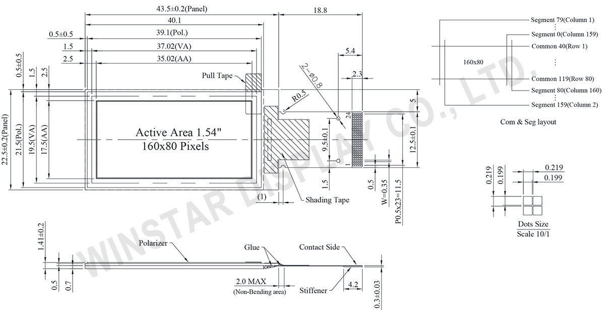
O WEO016080A é um display OLED gráfico COG de 1,54 polegadas com resolução de 160x80 pontos. Ele mede 43,5 x 22,5 mm com área ativa de 35,02 x 17,50 mm, e seu perfil fino de 1,41 mm é atribuído à sua estrutura COG.

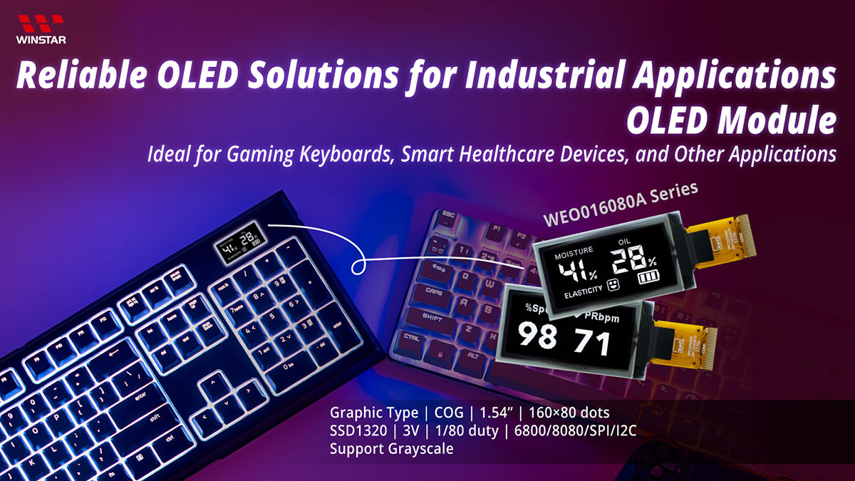
Equipado com o circuito integrado SSD1320, este módulo suporta interfaces 6800/8080 8-bit, SPI de 4 fios e I2C. Ele oferece escala de cinza de 4-bit (16 Levels) e alcança uma impressionante taxa de contraste de 10000:1.

Funcionando com uma faixa de tensão de alimentação lógica de 1,65V a 3,3V (tipicamente 3,0V), o módulo opera de forma confiável em temperaturas de -40°C a +80°C, com capacidade de armazenamento de -40°C a +85°C.

Ideal para uma variedade de aplicações incluindo produtos de rede, testadores USB, smartwatches, teclados para jogos e dispositivos de saúde inteligentes como oxímetros e analisadores de pele, o WEO016080A melhora a qualidade de exibição com sua tela nítida e vibrante.

Com sua alta resolução (160x80 pixels) e baixo consumo de energia, este módulo de display OLED é perfeitamente adequado para aplicações orientadas para o desempenho e eficiência.


Módulo de display OLED SSD1320 de 1,54 polegadas 160x80 - WEO016080A

DRAWING

1.54 inch 160x80 SSD1320 OLED Display Module - WEO016080A

Data source ref:WEO016080AWPP3N00000

SPECIFICATIONS

Dados Mecânicos

Item Dimensão Unidade
Matriz de pontos 160 x 80 Pontos
Dimensão do módulo 43.5 x 22.5 x 1.41 mm
Área ativa 35.02 x 17.50 mm
Tamanho do ponto 0.199 x 0.199 mm
Distância entre pontos 0.219 x 0.219 mm
Modo de exibição Passive Matrix
Cor de exibição Monochrome
Drive Duty 1/80 Duty
Gray Scale 4 bits
Interface 6800,8080,4-Wire SPI,I2C
IC SSD1320
Tamanho 1,54 polegadas

Classificações Máximas Absolutas

Parameter Símbolo Valor Min Valor Típico Valor Máximo Unidade
Supply Voltage for Logic VDD -0.3 4 V
Supply Voltage for Display VCC 0 19 V
Temperatura de operação TOP -40 +80 °C
Temperatura de armazenamento TSTG -40 +85 °C

Características Eletrônicas

DC Características Eletrônicas

Item Símbolo Condição Valor Min Valor Típico Valor Máximo Unidade
Supply Voltage for Logic VDD 1.65 3.0 3.3 V
Supply Voltage for Display VCC 8.0 15.0 15.5 V
High Level Input VIH 0.8×VDD VDD V
Low Level Input VIL 0 0.2×VDD V
High Level Output VOH 0.9×VDD VDD V
Low Level Output VOL 0 0.1×VDD V
VCC Supply Current ICC VDD=3V,VCC=15V
Display 50% Pixel ON
14 21 mA

Função do pino de interface

No. Símbolo Função
1 N.C.
(GND)
Reserved Pin (Supporting Pin)
The supporting pin can reduce the influences from stresses on the function pins.
This pin could be connected to external ground as the ESD protection circuit.
2 VCC Power Supply for OEL Panel
This is the most positive voltage supply pin of the chip. It must be connected to external source.
3~4 N.C. Reserved Pin
The N.C. pin between function pins are reserved for compatible and flexible design.
5 BS1 Communicating Protocol Select
These pins are MCU interface selection input. See the following table:
  BS1 BS2
I2C 1 0
4-wire SPI 0 0
8-bit 68XX Parallel 0 1
8-bit 80XX Parallel 1 1
6 BS2
7 VSS Ground of Logic Circuit
This is a ground pin. It also acts as a reference for the logic pins. It must be connected to external ground.
8 IREF Current Reference for Brightness Adjustment
This pin is segment current reference pin. A resistor should be connected between this pin and VSS. Set the current at 10μA maximum.
9 CS# Chip Select
This pin is the chip select input. The chip is enabled for MCU communication only when CS# is pulled low.
10 RES# Power Reset for Controller and Driver
This pin is reset signal input. When the pin is low, initialization of the chip is executed. Keep this pin pull high during normal operation.
11 D/C# Data/Command Control
This pin is Data/Command control pin. When the pin is pulled high, the input at
D7~D0 is treated as display data. When the pin is pulled low, the input at
D7~D0 will be transferred to the command register.
In I2C mode, this pin acts as SA0 for slave address selection.
12 R/W# Read/Write Select or Write
This pin is MCU interface input.
When interfacing to a 68XX-series microprocessor, this pin will be used as
Read/Write (R/W#) selection input. Pull this pin to “High” for read mode and pull it to “Low” for write mode.
When 80XX interface mode is selected, this pin will be the Write (WR#) input.
Data write operation is initiated when this pin is pulled low and the CS# is pulled low.
When serial mode is selected, this pin must be connected to VSS.
13 E/RD# Read/Write Enable or Read
This pin is MCU interface input.
When interfacing to a 68XX-series microprocessor, this pin will be used as the
Enable (E) signal. Read/write operation is initiated when this pin is pulled high and the CS# is pulled low.
When connecting to an 80XX-microprocessor, this pin receives the Read (RD#) signal. Data read operation is initiated when this pin is pulled low and CS# is pulled low.
When serial mode is selected, this pin must be connected to VSS.
14 D0 Host Data Input/Output Bus
These pins are bi-directional data bus connecting to the MCU data bus.
Unused pins are recommended to tie LOW.
When serial interface mode is selected, D2, D1 should be tied together as the serial data input: SDIN, and D0 will be the serial clock input: SCLK.
When I2C mode is selected, D2, D1 should be tied together and serve as SDAout,
SDAin in application and D0 is the serial clock input, SCL.
15 D1
16 D2
17 D3
18 D4
19 D5
20 D6
21 D7
22 VDD Power Supply for Logic
This is a voltage supply pin. It must be connected to external source.
23 VCOMH Voltage Output High Level for COM Signal
This pin is the input pin for the voltage output high level for COM signals. A tantalum capacitor should be connected between this pin and VSS.
24 VCC Power Supply for OEL Panel
This is the most positive voltage supply pin of the chip. It must be connected to external source.

Related Products

go top
close

Valorizamos sua privacidade

Ao clicar em "Permitir todos os cookies", você concorda com o armazenamento de cookies no seu dispositivo para melhorar a navegação no site, analisar o uso do site e auxiliar nossos esforços de marketing e desempenho. Você pode encontrar mais informações sobre esse assunto em nossa política. Política de privacidade

Valorizamos sua privacidade

A Winstar e certos terceiros utilizam cookies no site www.winstar.com.tw. Os detalhes sobre os tipos de cookies, sua finalidade e as partes terceiras envolvidas estão descritos abaixo e em nossa Política de Cookies. Clique em “Permitir todos” para consentir o uso de cookies e obter a melhor experiência possível em nossos sites. Você também pode definir suas preferências ou rejeitar cookies (exceto os estritamente necessários).

Gerenciar preferências de consentimento

Sempre ativo
Cookies essenciais

Esses cookies são essenciais para permitir que você navegue pelo site e utilize seus recursos, como definir suas preferências de privacidade, fazer login ou preencher formulários.

Cookies de análise

Também conhecidos como "cookies estatísticos", esses cookies coletam informações sobre como você utiliza um site, como quais páginas você visitou e em quais links você clicou. Veja os detalhes.