Startseite Produkte OLED-Anzeige Grafik-OLED-Anzeigen WEO016080A

1,54 Zoll 160x80 SSD1320 OLED Display Modul

Modellnummer WEO016080A

►1,54 Zoll OLED
►Typ: Grafik
►Bauweise: COG
►160x80 Punktmatrix
►IC:SSD1320
►3-V-Stromversorgung
►1/80 duty
►Schnittstelle: 6800, 8080, SPI, I2C
►die Farbe des Displays: Weiß
►Unterstützt Grauskala

Beschreibung

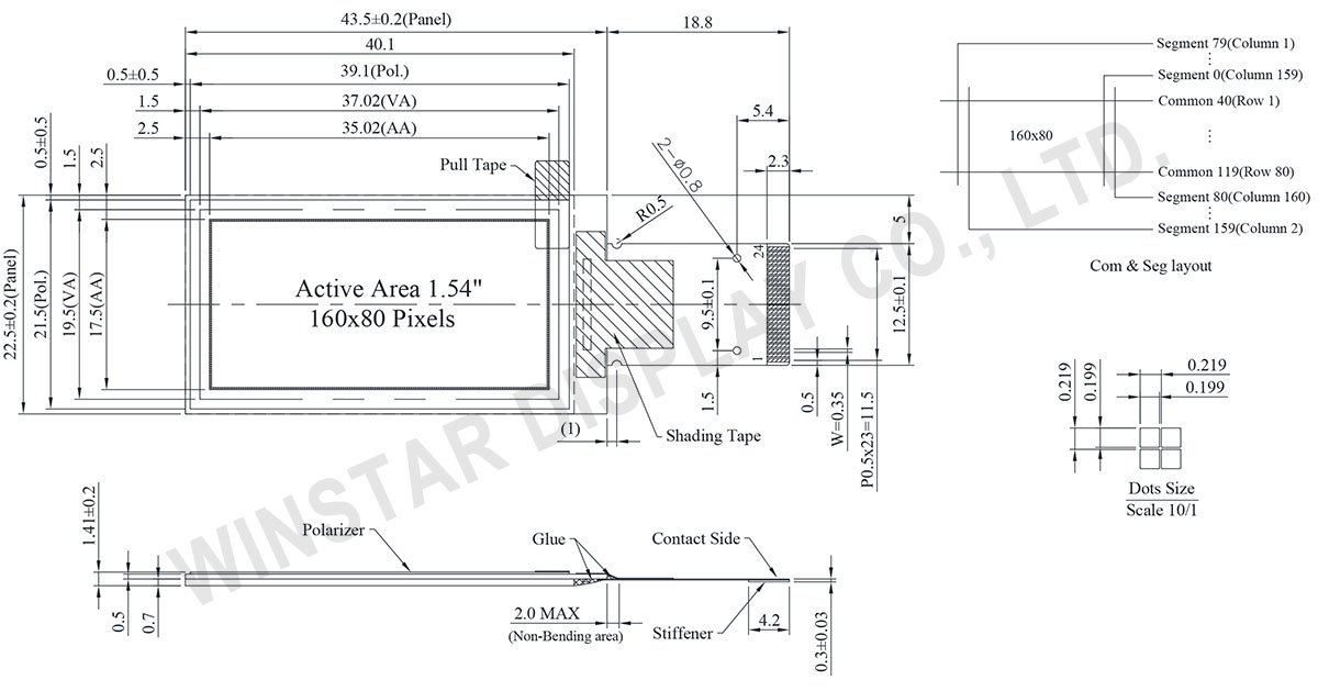
Der WEO016080A ist ein 1,54-Zoll COG-Grafik-OLED-Display mit einer Auflösung von 160x80 Pixeln. Er hat Abmessungen von 43,5 x 22,5 mm und eine aktive Fläche von 35,02 x 17,50 mm, bei einer schlanken Profilstärke von nur 1,41 mm dank seiner COG-Struktur.

Ausgestattet mit dem SSD1320 IC unterstützt dieses Modul 6800/8080 8-Bit, 4-Draht SPI und I2C Schnittstellen. Es bietet 4-bit (16 Levels) Graustufen und erreicht ein beeindruckendes Kontrastverhältnis von 10000:1.

Betrieben mit einer logischen Versorgungsspannung von 1,65V bis 3,3V (typischerweise 3,0V), arbeitet das Modul zuverlässig in einem Temperaturbereich von -40°C bis +80°C, mit einer Lagerfähigkeit von -40°C bis +85°C.

Ideal für eine Vielzahl von Anwendungen wie Netzwerkprodukte, USB-Tester, Smartwatches, Gaming-Tastaturen und Smart Healthcare-Geräte wie Pulsoximeter und Hautanalysatoren, verbessert der WEO016080A die Displayqualität mit seinem klaren und lebendigen Bildschirm.

Dank seiner hohen Auflösung (160x80 Pixel) und niedrigem Stromverbrauch eignet sich dieses OLED-Displaymodul perfekt für leistungsstarke und effiziente Anwendungen.


1,54 Zoll 160x80 SSD1320 OLED Display Modul - WEO016080A

Zeichnung

1.54 inch 160x80 SSD1320 OLED Display Module - WEO016080A

Data source ref:WEO016080AWPP3N00000

Technische Daten

mechanische Daten

Artikel Ausmaß Einheit
Punktmatrix 160 x 80 Punkte
Abmaße der modul 43,5 x 22,5 x 1,41 mm
Aktiver Bereich 35,02 x 17,50 mm
Pixelgröße 0,199 x 0,199 mm
Pixelabstand 0,219 x 0,219 mm
der Anzeigemodus Passive Matrix
die Farbe des Displays Monochrome
Drive Duty 1/80 Duty
Gray-Scale 4 bits
Schnittstelle 6800,8080,4-Wire SPI,I2C
IC SSD1320
Größe 1,54 Zoll

absolute Grenzwerte

Parameter Symbol Mindestwert Typ. Maximalwert Einheit
Supply Voltage for Logic VDD -0,3 4 V
Supply Voltage for Display VCC 0 19 V
Betriebstemperatur TOP -40 +80 °C
Lagertemperatur TSTG -40 +85 °C

elektronische Eingenschaften

DC elektronische Eingenschaften

Artikel Symbol Bedingung Mindestwert typischer Wert Maximalwert Einheit
Supply Voltage for Logic VDD 1,65 3,0 3,3 V
Supply Voltage for Display VCC 8,0 15,0 15,5 V
High Level Input VIH 0,8×VDD VDD V
Low Level Input VIL 0 0,2×VDD V
High Level Output VOH 0,9×VDD VDD V
Low Level Output VOL 0 0,1×VDD V
VCC Supply Current ICC VDD=3V,VCC=15V
Display 50% Pixel ON
14 21 mA

Schnittstelle Pin-Funktion

No. Symbol Funktion
1 N.C.
(GND)
Reserved Pin (Supporting Pin)
The supporting pin can reduce the influences from stresses on the function pins.
This pin could be connected to external ground as the ESD protection circuit.
2 VCC Power Supply for OEL Panel
This is the most positive voltage supply pin of the chip. It must be connected to external source.
3~4 N.C. Reserved Pin
The N.C. pin between function pins are reserved for compatible and flexible design.
5 BS1 Communicating Protocol Select
These pins are MCU interface selection input. See the following table:
  BS1 BS2
I2C 1 0
4-wire SPI 0 0
8-bit 68XX Parallel 0 1
8-bit 80XX Parallel 1 1
6 BS2
7 VSS Ground of Logic Circuit
This is a ground pin. It also acts as a reference for the logic pins. It must be connected to external ground.
8 IREF Current Reference for Brightness Adjustment
This pin is segment current reference pin. A resistor should be connected between this pin and VSS. Set the current at 10μA maximum.
9 CS# Chip Select
This pin is the chip select input. The chip is enabled for MCU communication only when CS# is pulled low.
10 RES# Power Reset for Controller and Driver
This pin is reset signal input. When the pin is low, initialization of the chip is executed. Keep this pin pull high during normal operation.
11 D/C# Data/Command Control
This pin is Data/Command control pin. When the pin is pulled high, the input at
D7~D0 is treated as display data. When the pin is pulled low, the input at
D7~D0 will be transferred to the command register.
In I2C mode, this pin acts as SA0 for slave address selection.
12 R/W# Read/Write Select or Write
This pin is MCU interface input.
When interfacing to a 68XX-series microprocessor, this pin will be used as
Read/Write (R/W#) selection input. Pull this pin to “High” for read mode and pull it to “Low” for write mode.
When 80XX interface mode is selected, this pin will be the Write (WR#) input.
Data write operation is initiated when this pin is pulled low and the CS# is pulled low.
When serial mode is selected, this pin must be connected to VSS.
13 E/RD# Read/Write Enable or Read
This pin is MCU interface input.
When interfacing to a 68XX-series microprocessor, this pin will be used as the
Enable (E) signal. Read/write operation is initiated when this pin is pulled high and the CS# is pulled low.
When connecting to an 80XX-microprocessor, this pin receives the Read (RD#) signal. Data read operation is initiated when this pin is pulled low and CS# is pulled low.
When serial mode is selected, this pin must be connected to VSS.
14 D0 Host Data Input/Output Bus
These pins are bi-directional data bus connecting to the MCU data bus.
Unused pins are recommended to tie LOW.
When serial interface mode is selected, D2, D1 should be tied together as the serial data input: SDIN, and D0 will be the serial clock input: SCLK.
When I2C mode is selected, D2, D1 should be tied together and serve as SDAout,
SDAin in application and D0 is the serial clock input, SCL.
15 D1
16 D2
17 D3
18 D4
19 D5
20 D6
21 D7
22 VDD Power Supply for Logic
This is a voltage supply pin. It must be connected to external source.
23 VCOMH Voltage Output High Level for COM Signal
This pin is the input pin for the voltage output high level for COM signals. A tantalum capacitor should be connected between this pin and VSS.
24 VCC Power Supply for OEL Panel
This is the most positive voltage supply pin of the chip. It must be connected to external source.

Ähnliche Produkte

go top
close

Wir schätzen Ihre Privatsphäre

Durch Klicken auf „Alle Cookies zulassen“ stimmen Sie der Speicherung von Cookies auf Ihrem Gerät zu, um die Navigation auf der Website zu verbessern, die Nutzung der Website zu analysieren und unsere Marketing- und Leistungsbemühungen zu unterstützen. Weitere Informationen zu diesem Thema finden Sie in unserer Richtlinie. Datenschutzrichtlinie

Wir schätzen Ihre Privatsphäre

Winstar und bestimmte Drittparteien verwenden Cookies auf www.winstar.com.tw. Die Einzelheiten zu den Arten von Cookies, ihrem Zweck und den beteiligten Drittparteien sind unten sowie in unserer Cookie-Richtlinie beschrieben. Klicken Sie auf „Alle zulassen“, um unserer Verwendung von Cookies zuzustimmen und die bestmögliche Erfahrung auf unseren Websites zu erzielen. Sie können auch Ihre Präferenzen festlegen oder Cookies ablehnen (mit Ausnahme der unbedingt erforderlichen Cookies).

Einwilligungspräferenzen verwalten

Immer aktiv
Notwendige Cookies

Diese Cookies sind unerlässlich, um Ihnen das Navigieren auf der Website zu ermöglichen und ihre Funktionen zu nutzen, wie z. B. das Festlegen Ihrer Datenschutzpräferenzen, das Einloggen oder das Ausfüllen von Formularen.

Analyse-Cookies

Diese Cookies, auch als „Statistik-Cookies“ bekannt, sammeln Informationen darüber, wie Sie eine Website nutzen, z. B. welche Seiten Sie besucht und auf welche Links Sie geklickt haben. Siehe Details.