When integrating and promoting Smart Display products, the focus has primarily been on introducing their features and functions, with less emphasis on how to control a Smart Display from the host side. This article uses page switching as an example to demonstrate how a host sends commands to switch pages on a Smart Display.
This example uses a 5-inch high-brightness standard Smart Display with CAN bus communication. It is divided into two parts: simulation and implementation. GUI Builder is used to create a project and switch pages, while the generated Log is used to understand the command sequence for page switching.
Simulation
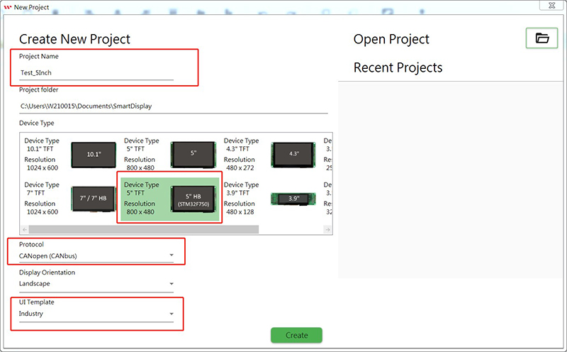
1-1 This example uses a 5-inch high-brightness Smart Display. Run GUI Builder to create a new project, enter the project name, select the 5-inch high-brightness template, select CAN bus as the communication protocol, and select Industry as the application scenario.
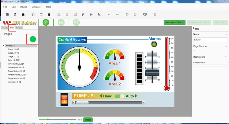
1-2 Select Page and click “+” to add a new page.
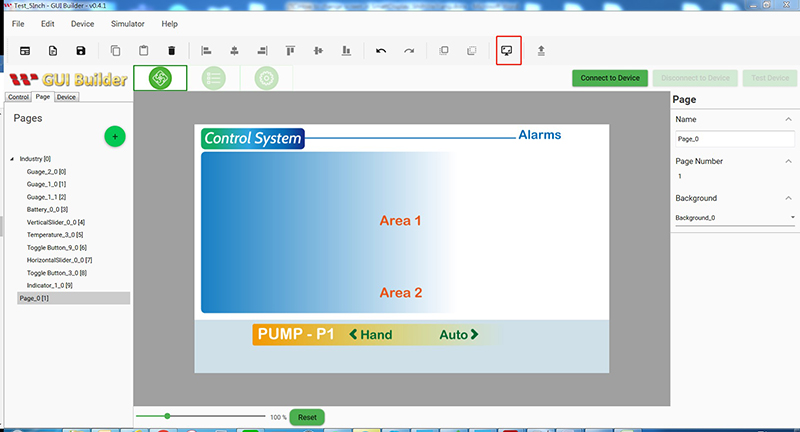
1-3 Click Simulator with GUI.
1-4
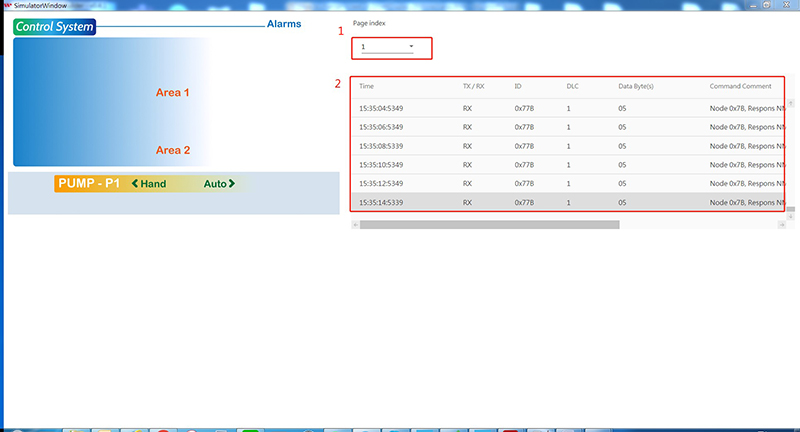
1. After entering the simulation window, select the page option. There are currently two pages, Page 0 and Page 1. Select Page 1 to switch to the other page.
2. The Log is displayed below. Right-click the Log to export it as an Excel file.
1-5
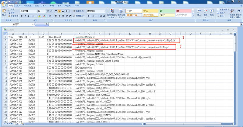
1. The Log shows that the host first sends a data request to Index 0x2104, sub-index 0x01 to change the mode to ConfigMode.
2. Next, the host sends a request to Index 0x2103, sub-index 0x02 to switch the page to Page 1.
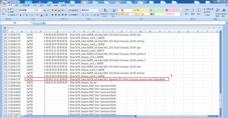
3. Finally, the host sends a data request to Index 0x2104, sub-index 0x01 to change the mode to DisplayMode.
Implementation
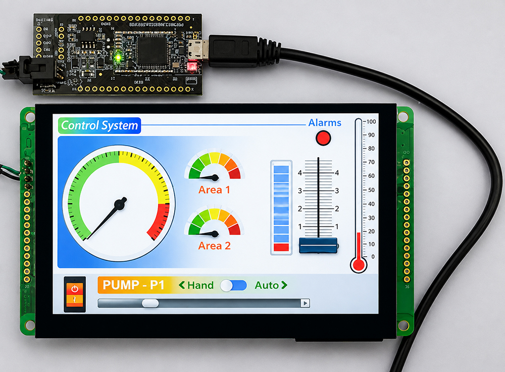
1-1 For the implementation, prepare a 5-inch high-brightness Smart Display module. Connect the CAN bus system interface of the Smart Display to the USB2CAN Dongle, as shown below. Run GUI Builder again and open the project used in the simulation above, or create a new project by following the steps below, and then connect to the Smart Display.
1-2 Select Page and click “+” to add a new page.
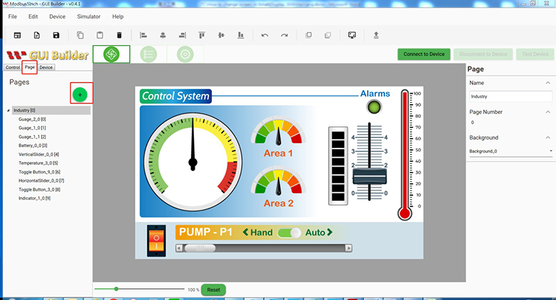
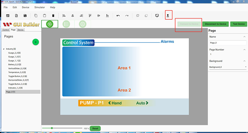
1-3 Click Connect to Device to establish the connection, and then select Upload the Project.
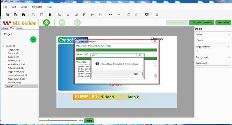
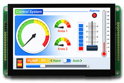
1-4 When the update is completed successfully, the following message appears and the module displays the screen shown below.
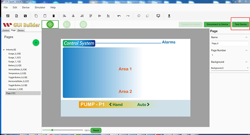
1-5 Click Test Device to enter the test screen.
1-6 The test screen appears as shown below.
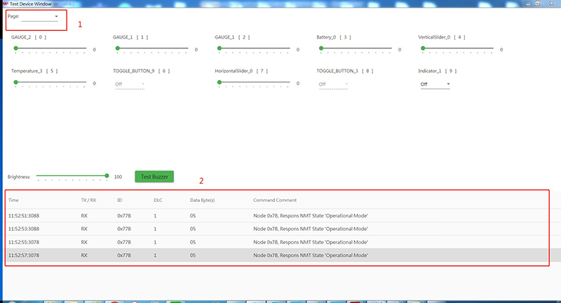
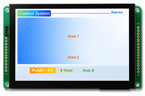
1. Select Page 1 from the Page menu. The module displays the screen shown below.
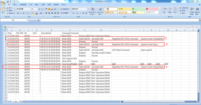
2. Right-click the Log to export it as an Excel file.
1-7
1. The Log shows that the host first sends a data request to Index 0x2104, sub-index 0x01 to change the mode to ConfigMode.
2. Next, the host sends a request to Index 0x2103, sub-index 0x02 to switch the page to Page 1.
3. Finally, the host sends a data request to Index 0x2104, sub-index 0x01 to change the mode to DisplayMode.
Conclusion
By switching pages through simulation and implementation, users can become more familiar with Smart Display operation. In addition to using GUI Builder for operation and simulation, users can review the Log to understand how commands are issued and how data is transmitted and received. This information can also serve as a reference when designing a custom host-side controller.