Impact of COVID-19 Epidemic – IC Shortage
Winstar R&D Team offers alternative solutions for optimizing products
Since the beginning of the COVID-19 pandemic, most countries in the world have implemented different lockdown policies. The automotive makers lacked confidence in market demand, misjudges the situation, reduced orders or even canceled orders at the beginning of the pandemic. However, the pandemic is fueling the growth of the Stay-at-Home Economy, Remote Working which has made cloud computing solutions demand getting stronger, medical equipment and 5G applications demand raising up.
Furthermore, the worldwide car market recovered faster than expected especially for EV car which caused the automotive chips demand raised up sharply by surprise. Governments of various countries have successively launched relevant economic revitalization programs, the market has seen a V-shaped recovery and increase orders. A confluence of several events brought the industry to the brink of exhausting its manufacturing capacity especially for chips (ICs). The status brings out a big problem was that strong demand for semiconductor chips used in PCs/laptops, cloud datacenters, AI clusters, games, medial and crypto-currency mining was already constraining the industry supply chain. In this unbalanced supply and demand situation, it also impacted the shortage of IC supply to panel makers, causing prices to rise or maintain at high levels, even cause many IC EOL or IC production reduced.
Facing with the situation of ICs EOL or ICs supply unstable, Winstar brings forward many alternative solutions to solve the problem. Without changing the display module and related hardware, with the smallest variable cost, continue to bring high-quality products to the market, and optimize the products, to be more competitive in the market, and offer profitable solutions for our customers.

Take Winstar standard product WO12864D3 solution as an example, the original STN-LCM design used IC ST7565P standard boost circuit, and the 4 times or 5 times voltage design is the most commonly used. When the supply of IC ST7565P is unstable or even IC shortage, customers can choose IC ST7567 as an alternative IC solution to solve the dilemma of material shortage.
Both ST7565P and ST7567 are single-chip dot matrix LCD driver ICs. The COG IC is the most commonly used in graphic module, which can be directly connected to the microprocessor bus 8-bit parallel or storage microprocessor, the serial display data sent in the internal display data RAM and chip generate an LCD drive signal independent of the microprocessor. Each data bit (65x132) of the internal Display Data RAM is 1-to-1correspondence with each pixel (65x132) on the LCD panel, therefore, ST7565P enables displays with a high degree of freedom. The display area can be expanded horizontally by using master/slave function. With various embedded circuit (2~6 times booster) have the advantages of circuit V0 regulator with LCD voltage contrast control, bias selection and R-C adjustment, voltage follower oscillation circuit. A system with the lowest display power consumption can be created for external components of high-performance portable devices.
The ST7567 IC is similar to ST7565P in basic function; it is not less than ST7565P in drive capability; it is relatively simple in terms of peripheral circuits. The differences between these two ICs in terms of hardware and software functions are shown below Table (1) and Table (2).
Table (1) Hardware comparison:
| Features | ST7565P | ST7567 | |
|---|---|---|---|
| Resolution | 132x64+1 | V | V |
| 132x54+1 | V | V | |
| 132x52+1 | V | X | |
| 132x32+1 | V | V | |
| 132x48+1 | V | V | |
| Interface | 6800 8-bit | V | V |
| 8080 8-bit | V | V | |
| 4-line SPI | V | V | |
| External components | 10 capacitors | 2 capacitors | |
| Vdd range | 2.4v~3.3v | 2.4v~3.3v | |
| Master/Slave mode | V | X | |
Table (2) Software comparison:
| Instructions | ST7565P | ST7567 |
|---|---|---|
| Display ON/OFF | V | V |
| Display start line set | V | V |
| Column address set upper bit | V | V |
| Column address set lower bit | V | V |
| Status read | V | V |
| Display data write | V | V |
| Display data read | V | V |
| ADC select reverse/normal | V | V |
| Display reverse/normal | V | V |
| Display all point on/off | V | V |
| LCD bias set | V | V |
| Read-modify-write | V | V |
| Read-modify-write end | V | V |
| Reset | V | V |
| COM output scan direction Reverse/normal |
V | V |
| Power control set | V | V |
| V0 voltage regulator internal resistor ratio set | V | V |
| Electronic volume set | V | V |
| Sleep mode set, normal/sleep | V | V |
| Booster ratio set | V | X |
| NOP | V | V |
| Test | V | V |
| Indicator Display Mode | V | X |
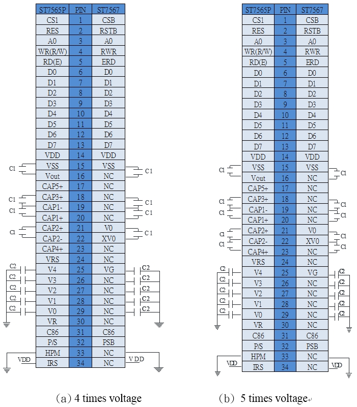
Here is an example shown as below figure1 (a). The ST7565P IC commonly used 4 times or 5 times boost circuit. Under the condition of total PIN numbers do not change, for keeping the same application peripheral circle, there are some changes in the pin define. In 4 times voltage design, CAP2+/- of ST7565P will be change to V0 and XV0 in ST7567 IC. And V4 (ST7565P) will be change to VG (ST7567 IC). The rest of the not used pins will be all set to NC in ST7567 IC.

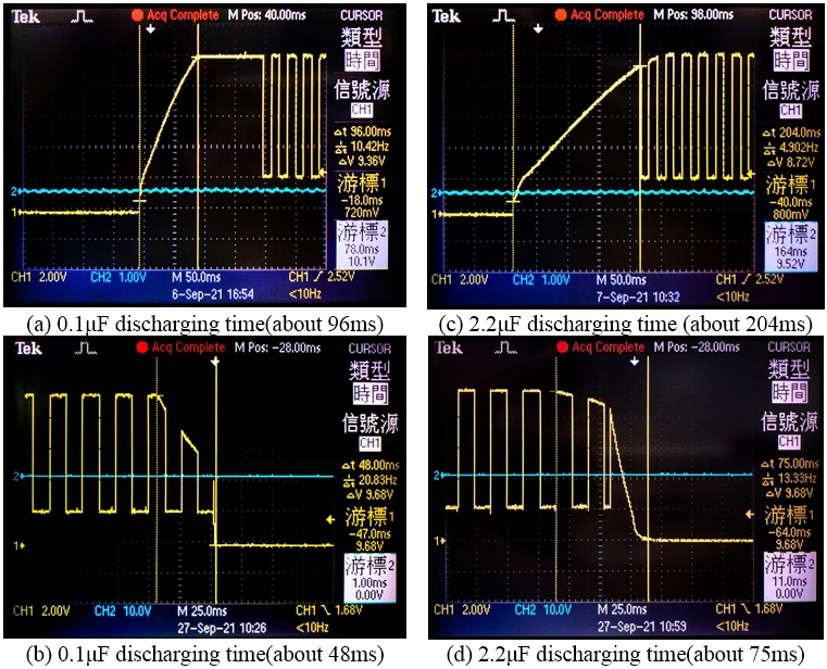
The recommend capacitance value is different between two ICs. The capacitance value of the CAP2+/- in ST7565P IC is maximum 2.2μF, as to ST7567 IC, the recommend capacitance value is 0.1μF. However, it does not affect the display image effect. The capacitance value only affects the charging and discharging time. And the effected time is very short, as shown in the figure below.

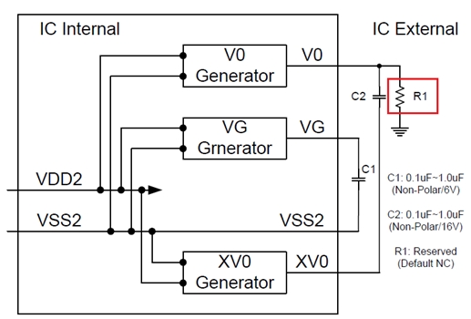
In the implement on the product application, using a capacitor value of 2.2μF, the discharge speed will be very fast, but it will not cause the phenomenon of image retention when shutting down. If there is a residual image during shutdown, it is recommended to change the capacitor to 0.1μF, or add a resistor to the circuit, and discharge it to improve it. The schematic diagram is shown in Figure 3.

Considering the voltage booster setting mode of the software, IC ST7567 is compatible with the original setting mode of the original IC ST7565P as below table:

The contrast voltage of display on the LCD, the software settings of the two ICs can also be the same. However, the original designs of these two ICs are still different. Therefore, according to the actual display effect, it still needs to be adjusted to the best display contrast. As shown in the below table.

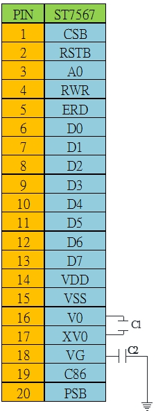
Take Winstar standard product WO12864H as the example of the solution, as shown in Figure 4. The design of the peripheral circuit using IC ST7567 is relatively simple, only two capacitors are needed (the recommended capacitor value is C1=0.1μF and C2=0.1μF); for the multiple of the boost, you only need to set it when the software is initialized. It can be 4 times or 5 times voltage. With the FPC design and the use of capacitors on the customer's original peripheral circuit, the customers can directly replace it without changing the hardware circuit, which is quite advantageous and simple in design and application.

Facing the impact of the epidemic and the rapid changes, Winstar R&D team is always stand with customers to face all challenges together, to be customer’s solution partner, solving problems for customers and moving forward together. Some existing STN models already been affected by the IC shortages or IC supply unstable, we released alternative models which corresponding IC have shorter lead-time. Please check the below as reference.
| Existing Model | Corresponding IC | Alternative Model | New IC |
|---|---|---|---|
| WO1602G | ST7032(i) | WO1602K | ST7032A(i) |
| WO1602H | ST7032(i) | WO1602L | ST7032A(i) |
| WO1602I | ST7032(i) | WO1602M | ST7032A(i) |
| WO12864A1 | ST7565P | WO12864M | ST7567 |
| WO12864B1 | ST7565P | WO12864N | ST7567 |
| WO12864C2 | ST7565P | WO12864P | ST7567S |
| WO12864D3 | ST7565P | WO12864Q | ST7567 |
| WO12864T | ST7565P | WO12864T1 | ST7567S |
| WO12864U | ST7565P | WO12864U1 | ST7567S |


