
Learning More About Smart Display RS485
1. Introduction
The previous technical article titled "SmartDisplay RS485 Introduction" provided a preliminary introduction to RS485 and Modbus protocol. In this article, we will further illustrate several commonly used techniques using multiple pages as examples. We will also explain the relevant specifications and technologies of SmartDisplay, including:
- How to switch pages using Button widget.
- Updating widget value after page switching.
- Use a buzzer to make sounds of different lengths
- Utilizing Graph widgets.
2. Materials
- A SmartDisplay with RS485 interface. In this case, we will use a 3.5" SmartDisplay.
- Arduino (Uno or Mega2560).
- Arduino RS485 expansion board (Link to DFRobot).
- Variable resistor (VR).
3. Wiring
- Variable Resistor: Connect Vcc to 5V. GND to GND. and the output to Arduino A0.
- Connect the A of the RS485 expansion board to SmartDisplay RS485+.
- Connect the B of the RS485 expansion board to SmartDisplay RS485-.
4. Example Content
This project consists of three pages, and each page can be switched using Button widget. The content and functionality of each page are as follows:
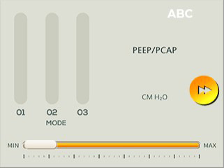
Page 1:
On the right side, there is a button to go to the next page, and below it, there is a Horizontal Slider to adjust the screen brightness. Preview image is as follows:
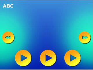
Page 2:
On the left side, there is a button to go back to the previous page, and on the right side, there is a button to go to the next page. Additionally, there are three buttons at the bottom that can emit short, medium, and long buzzer sounds respectively.
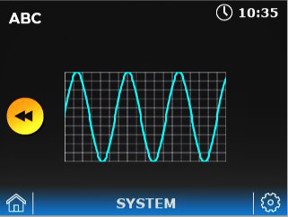
Page 3:
On the left side, there is a button to go back to the previous page. Simulate analog input using a variable resistor and display the results on a Graph widget.
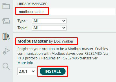
As the RS485 expansion board is used in this example, please download the library through the Library Manager before starting the programming:
5. Creating Page Content
First, use the GUI Builder to create the page content. The Text widget on each page can be directly filled with text, so there is no need to write it in the program.
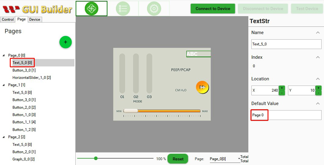
Please find the detailed widget content in the following table:
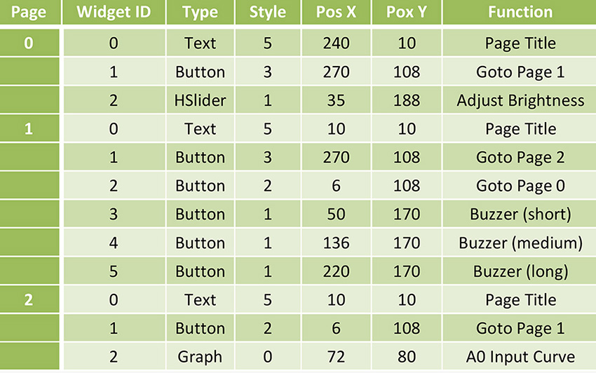
You can choose the SmartDisplay model based on the available materials and use different widgets to create different appearances. The only thing to note is that the widget ID and type on each page must match the definitions in the program. To simplify the process, it is recommended to create your page content based on the widget ID and type provided in this table.
Next, let's proceed to the programming part.
6. Explanation
(1) Include Files
After downloading the ModbusMaster library, make sure to include it using the #include directive:

Additionally, we have placed some SmartDisplay-related constants in SmartDisplayModbus.h for easier management. Make sure to include it as well.
(2) Widget ID to Register Conversion
In the previous article, the conversion method for widget ID to register address was explained as follows:
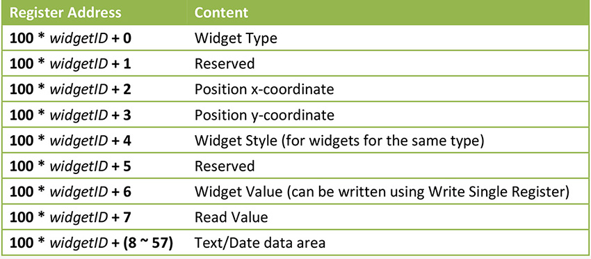
However, this form was designed when each page had a maximum of 10 widgets. Now, each page can have up to 64 widgets. This table still applies to the first 10 widgets, but for widgets beyond the 10th, we need to adjust to a new register block. Therefore, we have defined the following macros:
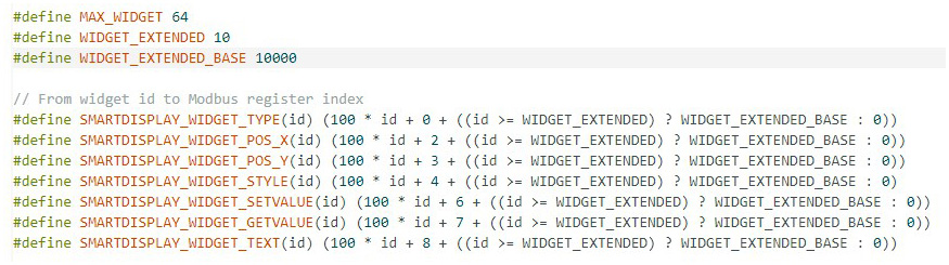
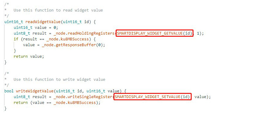
For ease of use, we define a function to read and write based on widget ID, and perform conversion in the function:
(3) Widget ID and GUI Design
When designing the page content using the GUI Builder, it was mentioned that the widget IDs must remain consistent. Therefore, the program defines the widget ID constants as follows:
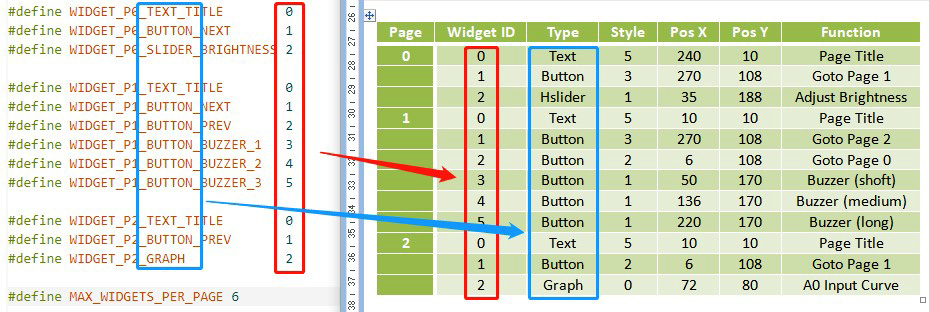
Using these constant definitions can help us remember the widget type and facilitate comparison with the actual page design. If the GUI design is modified in the future, remember to compare these values to avoid errors.
(4) Buzzer
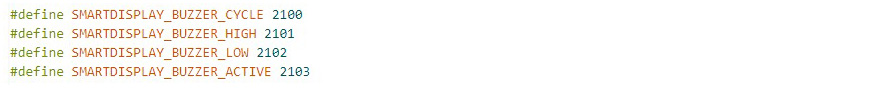
The firmware implements the buzzer sound by delaying the counter and then sending a 0/1 signal to the buzzer, and using other counters to control the start and stop times of the sound. To generate the sound, we need to write to four registers, including:
To adjust the duration of the sound, we can create a function that takes the parameter SMARTDISPLAY_BUZZER_HIGH to generate the sound. Here's an example of such a function:
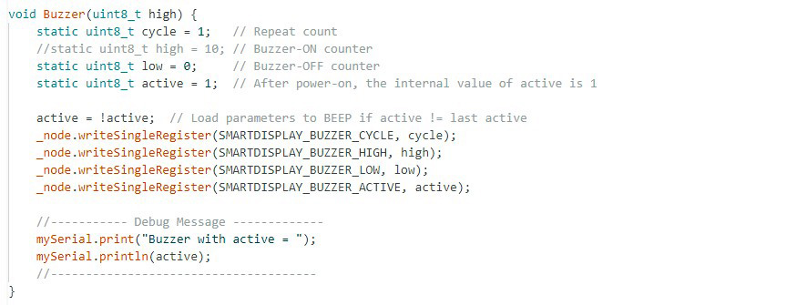
To ensure that the sound is only produced when the value of SMARTDISPLAY_BUZZER_ACTIVE is different from the previous write, we can make the variable exist in a static manner. Additionally, we can perform the reverse process before each call.
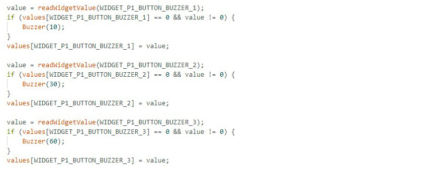
Finally, in the page handling function, you can generate sounds of different durations based on the button states:
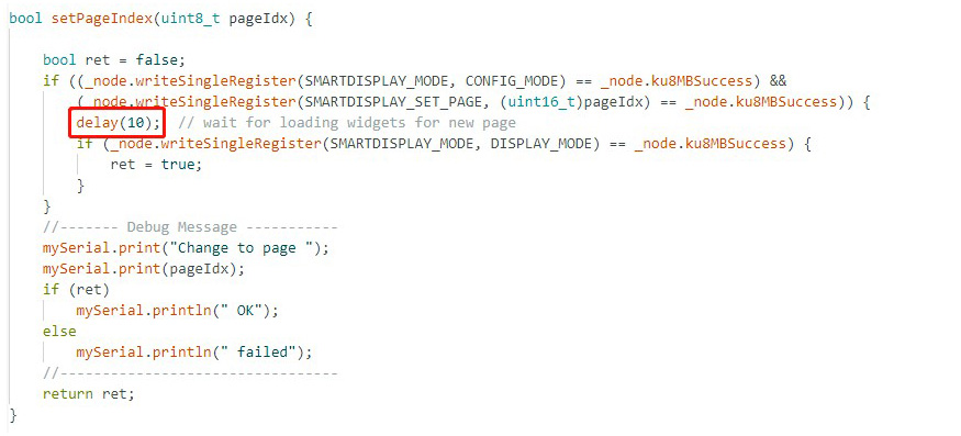
(5) Page Switching
Before switching pages, it is necessary to enter CONFIG_MODE. After configuring the new page, it can be set to DISPLAY_MODE. When switching pages, the SmartDisplay will reload all the widgets on the new page. To avoid performing read/write actions before the SmartDisplay finishes the reload process, it is common to add a delay to allow for sufficient time. The length of this delay depends on the complexity of the page. If any abnormal behavior is observed after switching pages, you can try increasing the delay time to see if it resolves the issue.
After switching pages, the widgets on the new page have default values. Therefore, we establish a process to handle page switching, record widget values, and restore widget values.
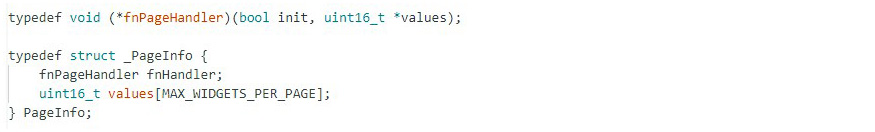
First, let's define a function pointer for page handling to facilitate the creation of a page table and assign a handling function to each page:
And create a page table:
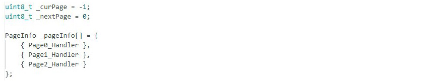
The constant MAX_WIDGETS_PER_PAGE defines the number of widgets to record values for on each page. If you add more widgets in the future, make sure to update this value accordingly.
Finally, in the loop() function, you can handle the page switching and widget processing:
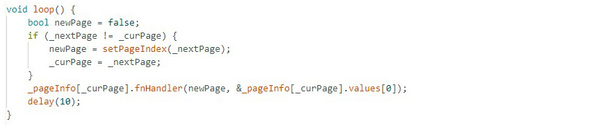
If the current page _curPage is not equal to the next page _nextPage, set the page switch flag newPage to true. This way, the page handling function will know that initialization is required. Let's take Page0 as an example:
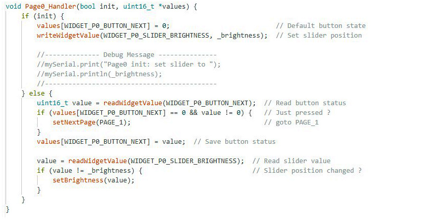
If the init parameter is true, indicating that we have just entered the page, we set the value of WIDGET_P0_BUTTON_NEXT to 0. This is because when we switch to a new page, the button's default value is 0. We want to execute specific commands (in this case, switching to PAGE_1) only when the button is pressed (when the value changes from 0 to 1). Therefore, we need to reset it to 0 (as it might have already been changed to 1 previously).
For the Slider widget, its initial value is also 0 when loaded. However, it may have been modified previously to adjust the brightness. Therefore, we need to restore it to the current brightness value _brightness.
In other cases (init is false), we can handle the widgets differently based on whether they have changed. Finally, we save the values of all the widgets for reference in the next processing cycle.
As for setting the next page _nextPage, you can use the following function:

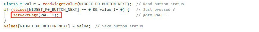
If the page handling function needs to check the content of widgets every time, and if it detects a button value change from 0 to 1, you can call a function to request a page switch. Here's an example of how you can achieve this:
(6) Graph Widget
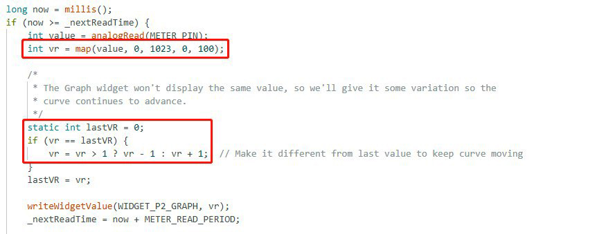
The Graph widget can visually represent the values that are written to it in the form of a graph. Here, we use a variable resistor connected to A0 to simulate an analog input, and we display the data variation using the Graph widget. Since the analog input range of Arduino is 0-1023, while the Graph widget accepts values from 0-100, we need to use the map() function to adjust the range.
The Graph widget was designed to update the display only when the value changes. If you want to achieve a periodic update effect, you can employ a little trick: periodically check the value, and if it remains the same as the last read value, slightly modify it (by adding or subtracting 1). This way, you can create the illusion of a periodic update with dynamic effects.
7. Conclusion
That concludes the explanation of this example program, and we hope it provides readers with a deeper understanding. This example can also serve as a starting framework for future projects, helping to reduce development time. You can access the entire program by downloading it from the following link: Modbus-MultiPageOperation on GitHub.
If you're unfamiliar with RS485/Modbus, you can refer to the previous explanation for more information: SmartDisplay RS485 Introduction.
