
How to send command to switch page on Smart Display via Modbus protocol
Preface
So far, as we know that a system interface and a communication protocol are required to control a smart display. System Integration controls Smart-Display products in a comprehensive manner. In all those ways, Arduino could be used from a host control perspective as well. This article provides an example of how to control Smart-Display products from the perspective of the client and host. So that it could be understood how the host issues a command to switch pages of the Smart-Display. As an example, let's create a demo scenario: In this, we take a physical button, pressing which will switch the smart display from the first page to the second page. And when the Smart Display is on the second page, pressing the physical button again will return to the first page.
Introduction
This application will take a 3.5-inches high-brightness standard product as an example. And the application file explains how to control the Smart Display ModBus 3.5” module to display switch page commands received from a host controller. The host is an Arduino mega 2560 board with a ModBus shield and a physical button. The application is developed in the below diagram.
The application is developed in the below diagram.
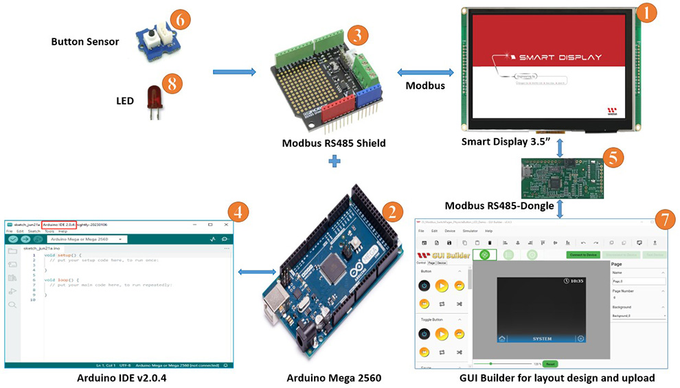
System Block Diagram
This application needs to require the below components:
- Smart Display ModBus 3.5”
- ARDUINO Mega 2560
- Modbus RS485 shield for ARDUINO Mega 2560
- Arduino IDE v2.0.4
- Modbus Dongle
- Physical button.
- Software GUI-Builder v0.4.2 or above.
- LED
The Demo is divided into three parts:
- Design the Demo Project in GUI Builder.
- Build and Upload the Project.
- Program the Arduino Host.
Design the Demo Project in GUI Builder
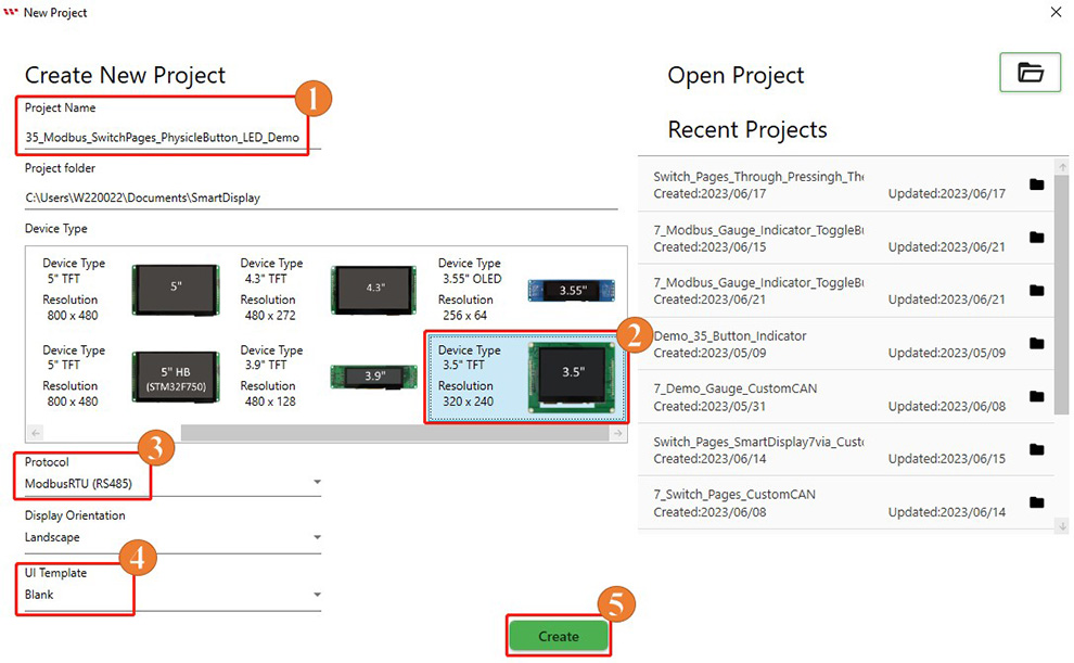
First of all, open an updated GUI builder to create a new project, and then type the project name, then check the project folder which is auto-selected by default. And then select the device type, which I have selected 3.5 ". Then select the protocol, then let the display orientation be by default landscape mode. And then select blank in the UI Template and finally click on the create button to create your new project, as shown in Fig.
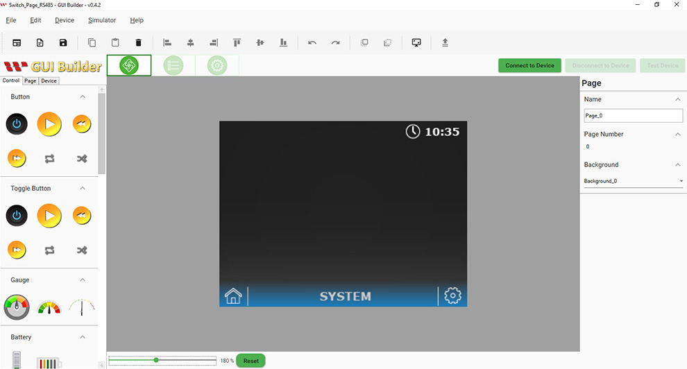
This page opens after creating the project.
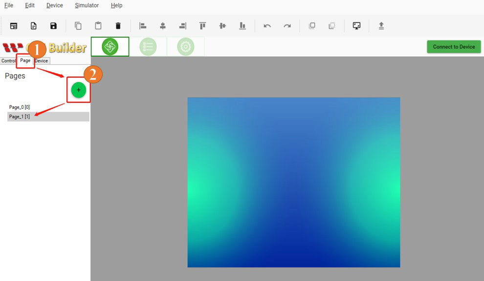
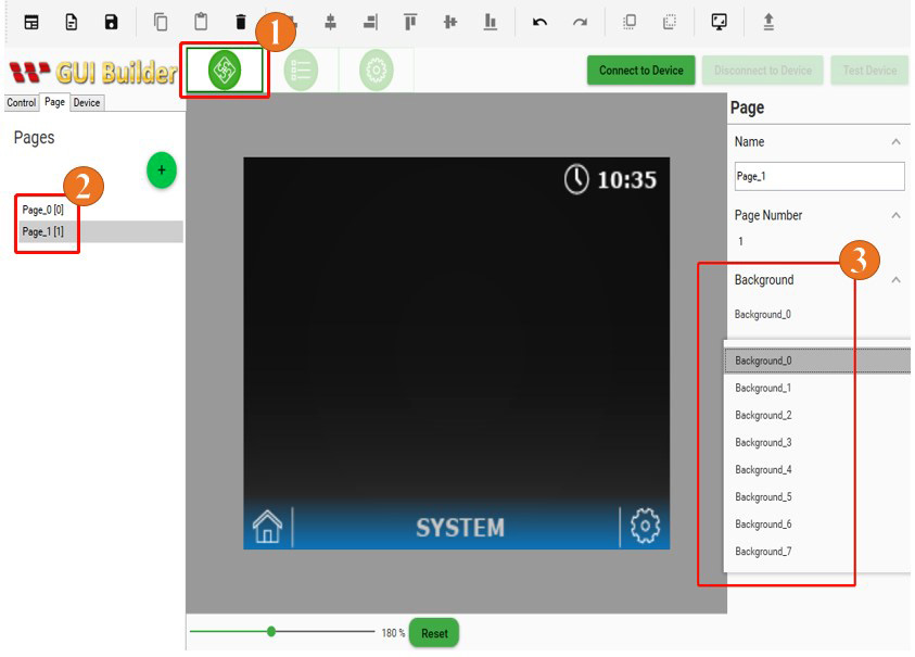
As per the demo scenario, one more page needs to be added. For this, click on the page button and then click on the plus button.
Background style could be changed in the resource panel
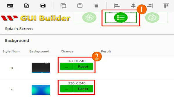
The background style could be changed in the page section also.
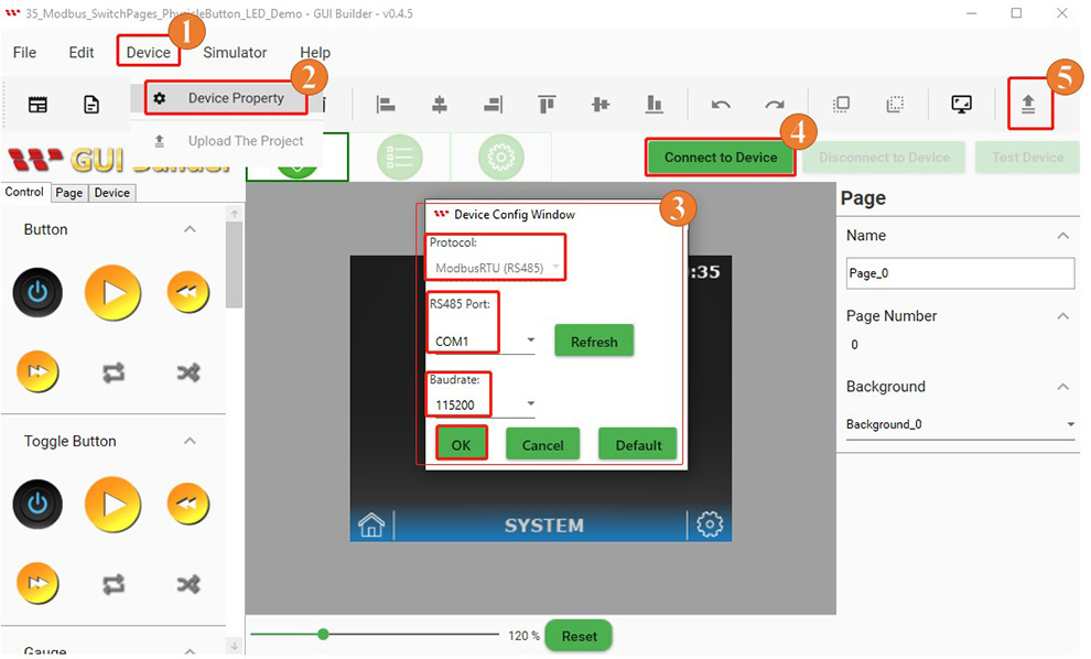
Build and Upload the Project
After completing all previous steps and created two different pages in previous steps. Now it's time to build the project. Switch to the "Page Info" page. Go to the "Device" button and select "Device Properties". Check all the details in the "Device Config Window". Then select the COM port, set the baud rate, and click the "OK" button. After that, click on the "Connect to Device" button to connect your smart display. Finally, click the "Upload" button to upload this project, as shown in the image below:
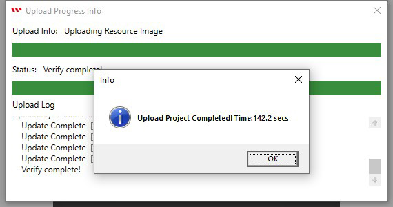
When the Upload project is completed then click on the ok button as shown below Fig:
The start screen will appear after uploading is completed as shown below Fig:
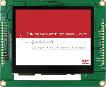
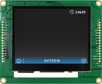
After the start screen, it will switch to the first page. Now Building and uploading has completed through GUI builder as shown below Fig:
Program the Arduino Host
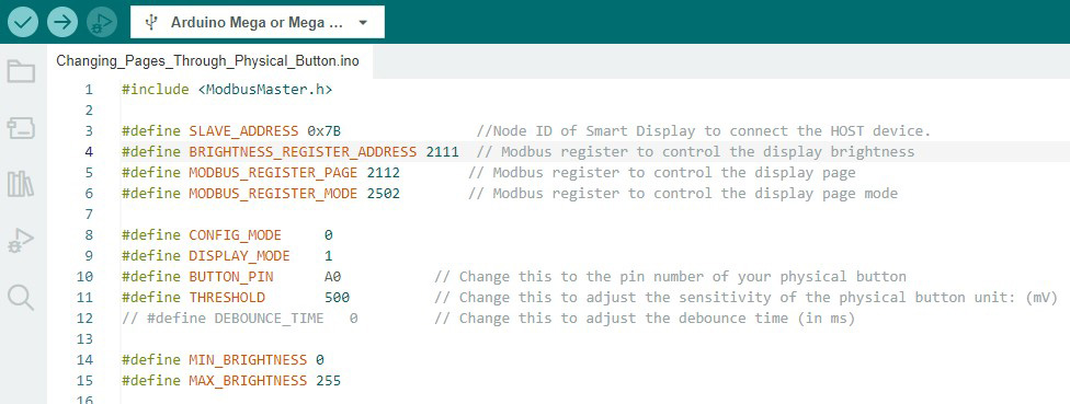
ModbusMaster library is used for the Modbus communication protocols. It is important to take note of address to connect host with SmartDisplay. If you want to learn more about how communication between the host and smart display is via RS485, please reference the GUI builder communication log. Here all required register address define in the Arduino IDE program as shown in below Fig:
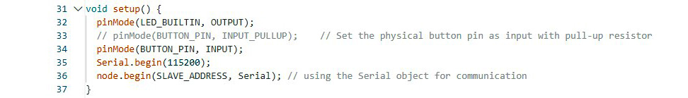
Define all pin mode and setup for external accessories like physical button and LED. Also setup the baud rate for serial communication as shown in below Fig:
The following figure shows that when the Arduino host reads the value change of the physical button, it will send the value to the Smart Display through the Modbus communication protocol to change the page.
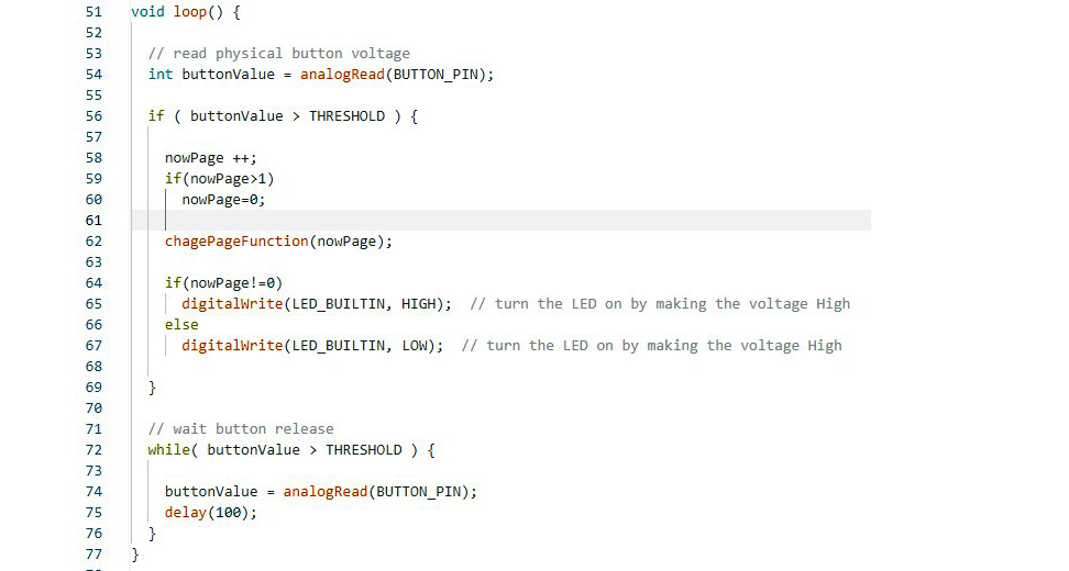
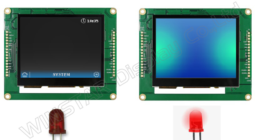
After successfully verifying and uploading this program through Arduino IDE. It may be possible to turn the page by pressing it via physical buttons. When the screen shows the first page the LED turns off and when the screen changes to the second page by pressing the physical button the LED turns on as shown in the picture below:
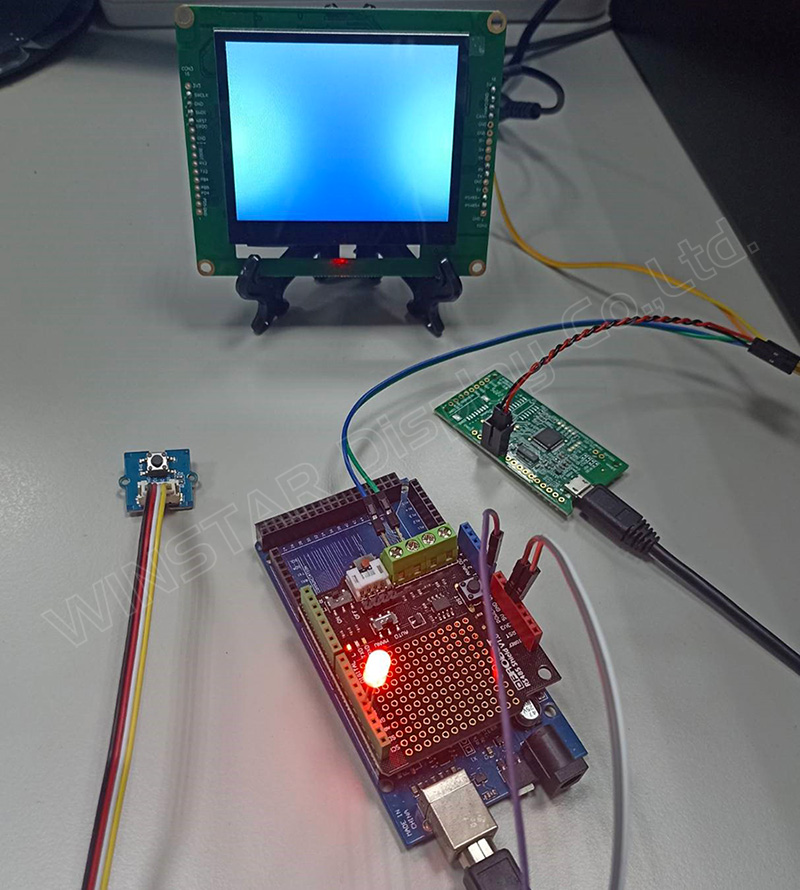
Please refer to this link of GitHub (https://bit.ly/3oT0o5M) to download the above program and can seek more details about this demo project. The actual hardware setup fig is given below. Note: Please follow this link for more details about Modbus RS485 shield which used in this demo project (https://media.digikey.com/pdf/Data%20Sheets/DFRobot%20PDFs/DFR0259_Web.pdf) .
Congratulations, the design demo is completed in Smart Display 3.5" with a physical button and LED to change the display while pressing the physical button.
Conclusion
The purpose of this article is to promote GUI builder operation and simulation. Through switching paging, users can understand how to design their own host-side controllers through various communication protocols. The user can also understand the receiving and sending of commands through the host. They can control and use the Smart Display in multiple ways.
