
How does HOST communicate with SmartDisplay via CANopen (LED and indicator control via physical and virtual buttons)
Preface
As we know that a system interface and a communication protocol are required to control a smart display. System integration Controls Smart-Display products in a comprehensive manner. In all those ways Arduino could be used from a host control perspective as well. This article provides an example of how to control Smart-Display products from the perspective of the client and host. So that it could be understood how the host issues a command to change the color of the Indicator with LED in the Smart-Display.
As an example, let's create a demo scenario: in this, we place a touch button on the screen and take a physical button. Pressing either the physical button or the touch button will change the color of the indicator on the screen and turn the external LED on or off.
Introduction
This application will take a 3.5-inches Smart Display standard product. This application file explains How to modify the program to add control Physical buttons, touch buttons, and indicators on the screen and a LED on board. And how commands received from a host controller. The host is an Arduino mega 2560 board with a CAN Bus shield.
The application is developed in the below diagram.
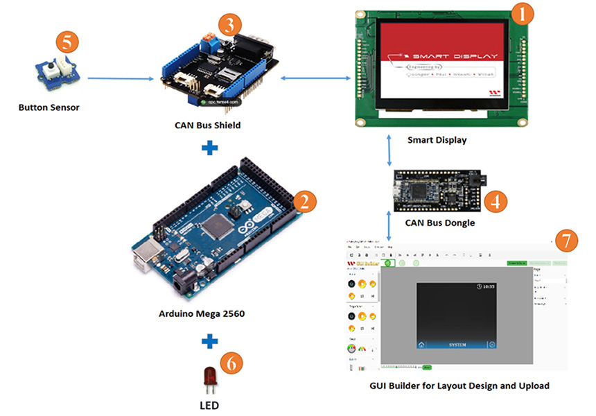
System Block Diagram
This application needs to require the below components:
- Smart Display
- ARDUINO Mega 2560
- CAN bus shield for ARDUINO Mega 2560
- CAN bus Dongle
- Physical Button Sensor
- LED
- Software GUI-Builder v0.4.2 or above
The Demo is divided into three parts:
- Design the Demo Project in GUI Builder.
- Build and Upload the Project.
- Program the Arduino Host.
Design the Demo Project in GUI Builder
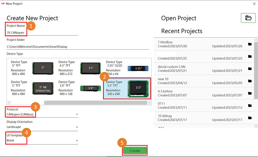
First of all, open an updated GUI builder to create a new project, and then type the any project name, then check the project folder which is auto-selected by default. And then select the device type, which I have selected 3.5 ". Then select the protocol, then let the display orientation be by default landscape mode. And then select blank in the UI Template and finally click on the create button to create your new project, as shown in Fig.
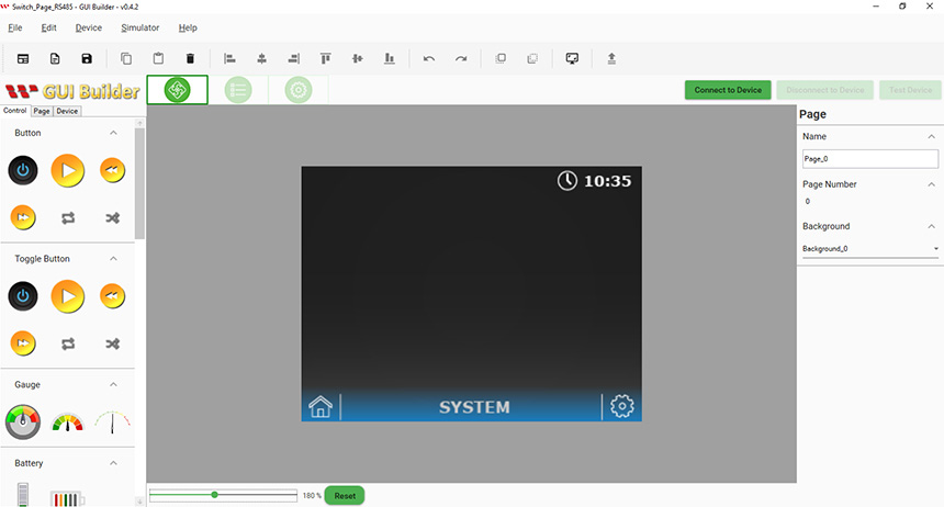
This page opens after creating the blank project.
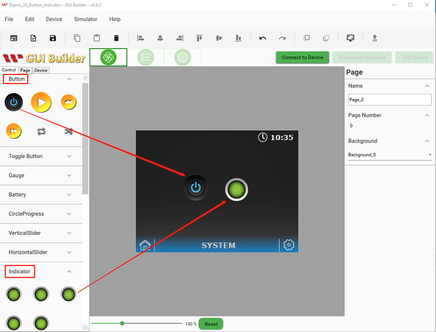
As per the demo scenario, needs to add a button and an Indicator from the control section. Need to select, drag, and drop as per the requirement.
Build and Upload the Project
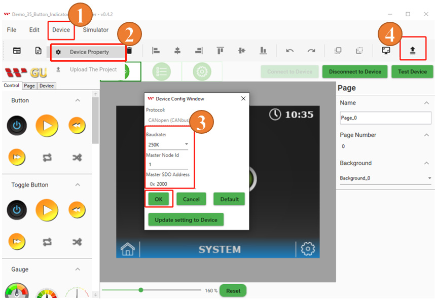
When all previous steps are completed and created the layout design. Now it's time to build the project. Go to the Device button and select Device Properties. Then select the default settings of the baud rate or choose according to your requirements. You do have the flexibility to adjust the baud rate to meet your specific needs. But it highly recommends that you set the baud rate in both your Arduino code and the GUI builder to the same value. Finally, click on the upload button to upload this project as shown below Fig:
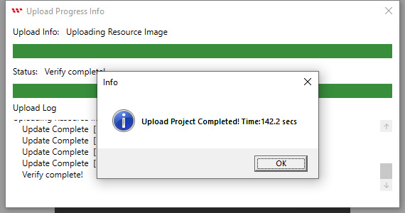
When the Upload project is completed then click on the ok button as shown below Fig:
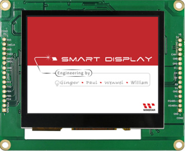
The start screen will appear after uploading is completed as shown below Fig:
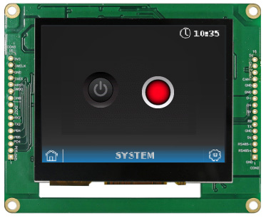
After the start screen, it will jump to the uploaded design page. Now Building and uploading has completed through GUI builder as shown below Fig:
Program the Arduino Host
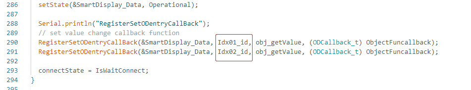
Arduino Integrated Development Environment version "IDE v2.0.4" is used for Arduino coding. There are mcp2515_can.h library and several more supportive libraries have been used for the CAN bus communication protocols. For more details, see the Arduino code. It is important to take note of the address to connect the host with Smart Display. If you want to learn more about how communication between the host and smart display is via CAN bus Shield, please reference the GUI builder communication log. Here all required register addresses are defined in the Arduino IDE program as shown below in Fig:
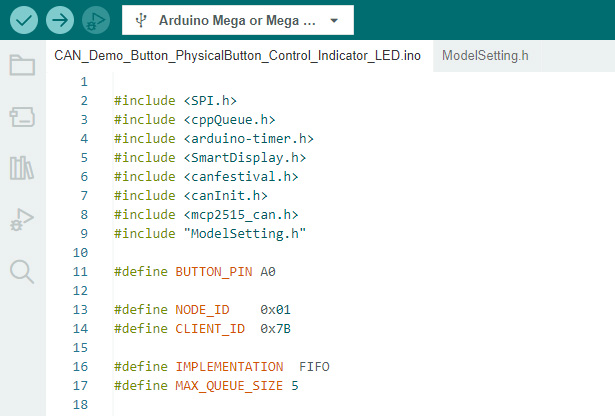
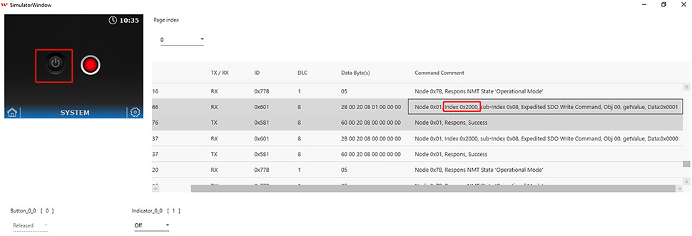
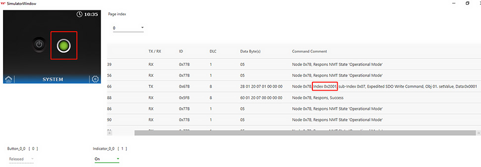
The index of the Button style corresponds to 0 (0x2000) and the index of the Indicator style corresponds to 1 (0x2001) is defined in the CAN open structure. It is important to take note of an object's index. An object's status can be changed while programming in the Arduino host if its index is known, showing as below in the Fig of simulation logs table.
Here the data type of the object is defined. If the user wants to add more items, then they need to be defined its data type here.
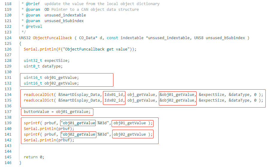
The following figure shows how the “ObjectFunCallback” call for receiving the value from each object. Users could modify or add more items below this code.
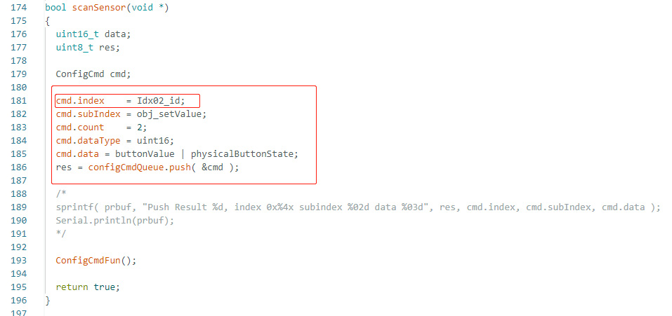
When the Arduino host receives the value change from the physical Button Sensor. It will send certain values to the Smart Display through the CAN open protocols. Please refer to the following program for key points "command structure ids and sub-indexes". The purpose of this program is to update the Indicator (object index 2) value according to the value changed from the physical Button Sensor.
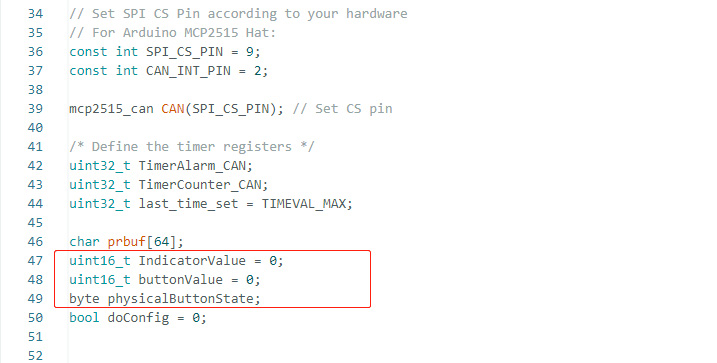
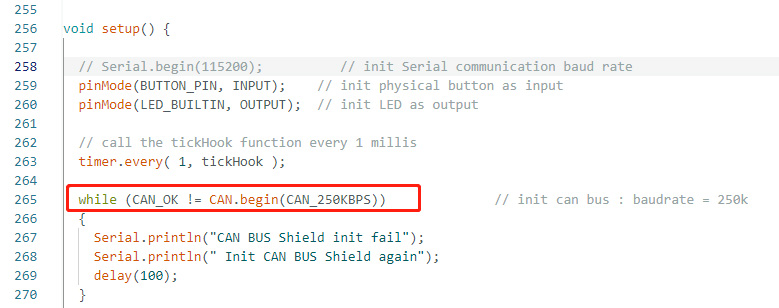
Define registers address for all objects, pin mode, and set up for external accessories like physical buttons and LED pins as input or output. Also setup the baud rate as shown below in Fig:
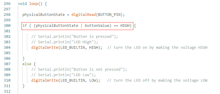
Finally, here defined the task in the loop to perform the decided scenario. When pressing either the physical button or the touch button will change the color of the indicator on the screen and turn the external LED on or off
Appendix:Set Up the Project
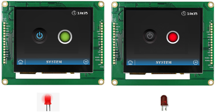
After successfully verifying and uploading this program through Arduino IDE. By pressing physical buttons or touch buttons it becomes possible to turn on the LED and change the indicator color to green. When the indicator shows a red color and the LED is off, it means that neither the physical button nor the touch button is pressed. As shown in the figure below:
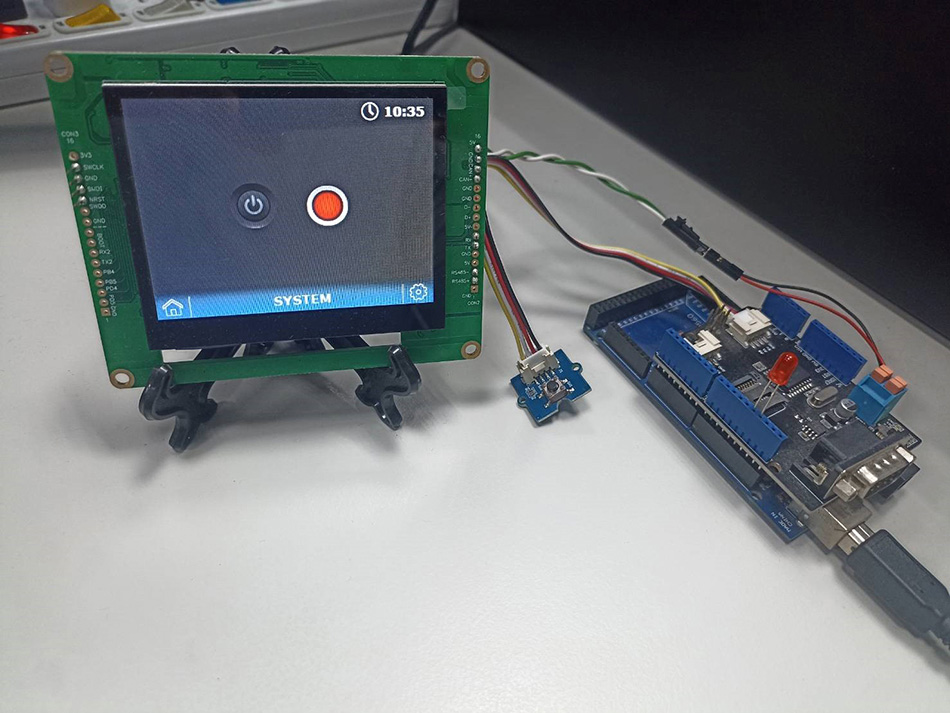
Please refer to this link of GitHub https://bit.ly/3oT0o5M to download the above program and can seek more details about this demo project and other demo project in example. The actual hardware setup fig is given below.
Congratulations, the design and demo of the Smart Display is completed with a physical button and LED to change the Inductor color while pressing the physical button or touch button.
Conclusion
The purpose of this article is to promote GUI builder operation and application. So the users can understand how to design their own host-side controllers through various communication protocols. The user can also understand the receiving and sending of commands through the host. They can seek all control over the Smart Display and use it in various ways.
