This example demonstrates how to use an Arduino board to switch pages on a standard 3.5-inch Smart Display module via Modbus RS485. The host controller uses an Arduino Mega 2560 with a Modbus RS485 shield, a physical button, and an LED.
In this demo, pressing the physical button switches the Smart Display from the first page to the second page. Pressing the button again switches the display back to the first page.

System Block Diagram
Required Components
- 3.5-inch Modbus Smart Display
- Arduino Mega 2560
- Modbus RS485 shield for Arduino Mega 2560
- Arduino IDE v2.0.4
- Modbus RS485 dongle
- Physical button
- GUI Builder v0.4.2 or later
- LED
Demo Workflow
- Design the project in GUI Builder
- Build and upload the project
- Program the Arduino host
Design the Project in GUI Builder
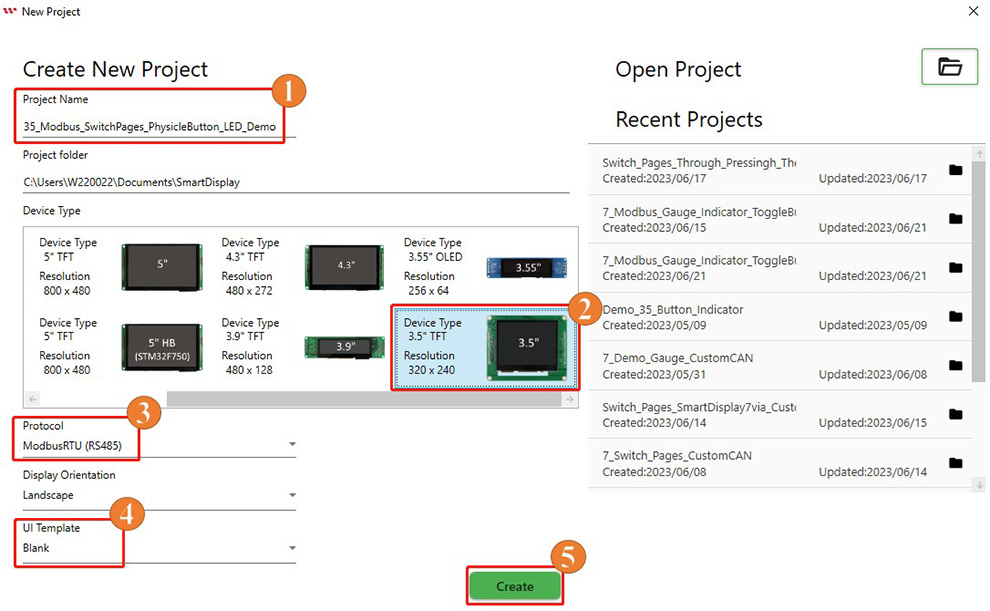
First, create a new project in GUI Builder and enter a project name. Select the 3.5-inch TFT device under "Device Type", select "ModbusRTU (RS485)" under "Protocol", and set the display orientation to Landscape. Next, select Blank under "UI Template", and then click "Create" to create the project, as shown below.
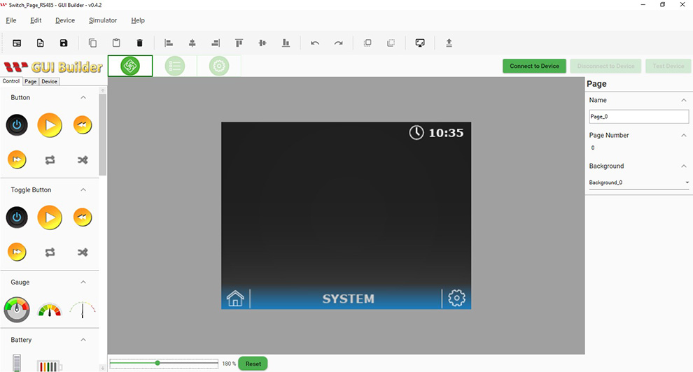
After the project is created, the initial page appears in GUI Builder.
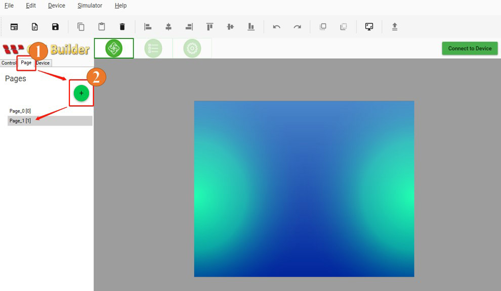
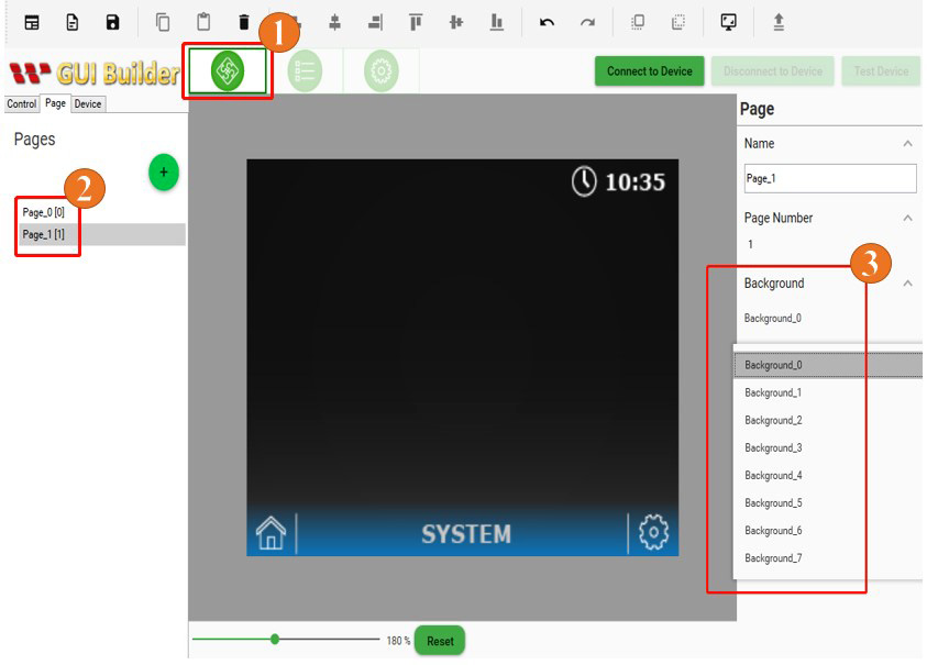
This demo uses two pages. Click "Page", and then click "+" to add the second page.
Background styles can be managed from the Resource section.
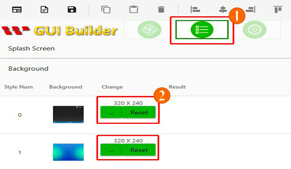
The desired background can then be selected for each page in the "Page" section.
Build and Upload the Project
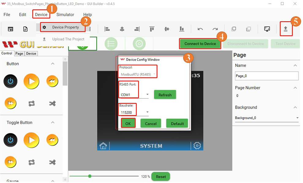
After designing the two pages, configure the connection settings and upload the project to the Smart Display. First, switch to the "Page Info" page, click "Device", and select "Device Property". In the Device Config Window, confirm that the protocol is set to "ModbusRTU (RS485)", select the appropriate COM port, and set the baud rate to match the Smart Display. Click "OK" to apply the settings, and then click "Connect to Device". Once the Smart Display is connected, click "Upload The Project" to upload the project.
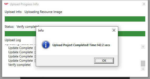
When the project upload is complete, click "OK".
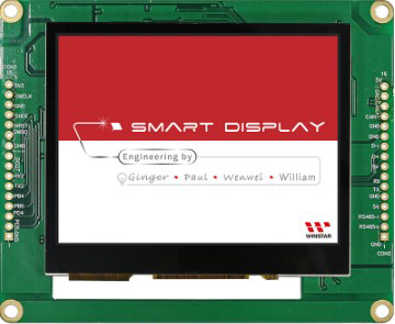
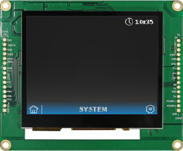
After the upload is complete, the startup screen appears on the Smart Display.
The Smart Display then switches from the startup screen to the first page, indicating that the project has been uploaded successfully.
Program the Arduino Host
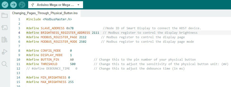
When using Modbus to connect the host to the Smart Display, it is important to use the correct register addresses in the program. For more information about RS485 communication between the host and the Smart Display, refer to the communication log in GUI Builder. The figure below shows the register address definitions required in the Arduino IDE program for this example.
Next, configure the pin modes and external components, such as the physical button and LED, and set the baud rate for serial communication.

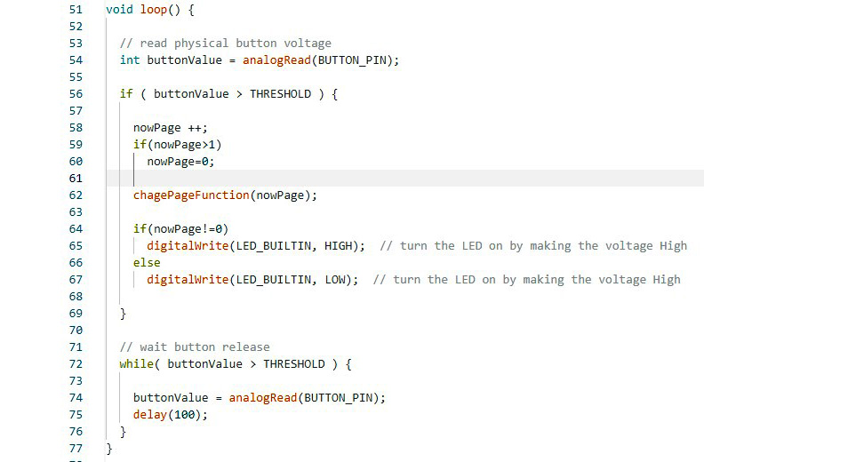
The figure below shows how the Arduino host detects a change in the physical button input and sends the corresponding value to the Smart Display via Modbus communication to switch the display page.
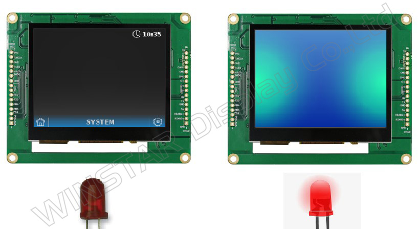
After verifying and uploading the program in Arduino IDE, the physical button can be used to switch pages on the Smart Display. The LED is off when the Smart Display shows the first page. When the physical button is pressed to switch to the second page, the LED turns on, as shown below.
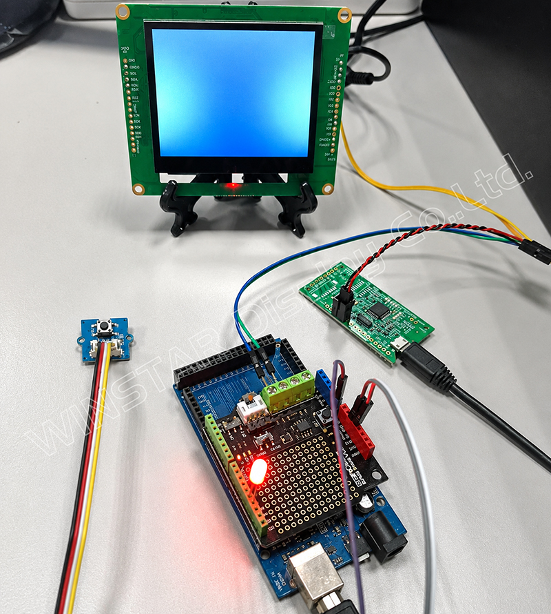
The Arduino program is available on GitHub, where you can find additional details about this demo project. The actual hardware setup is shown below. For more information about the Modbus RS485 shield used in this demo, refer to the technical documentation.
Conclusion
This example demonstrates how to use an Arduino Mega 2560 as the host controller to switch pages on a Smart Display via Modbus RS485. After creating the display pages and completing the required settings in GUI Builder, the Arduino host can switch between the two pages based on input from the physical button.
This example provides developers with a basic understanding of Modbus communication and control between an Arduino host and a Smart Display, and can serve as a reference for developing host-controlled Smart Display applications.