Home Products TFT Display High Brightness TFT Display WF24LSYAJDNN0

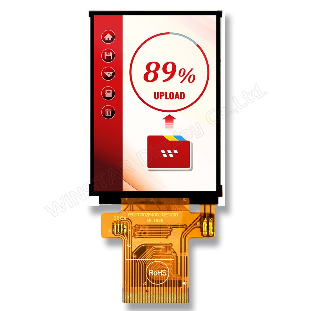
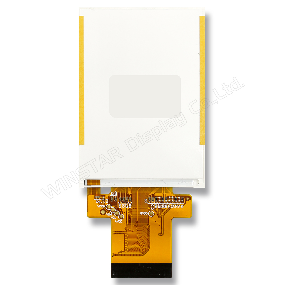
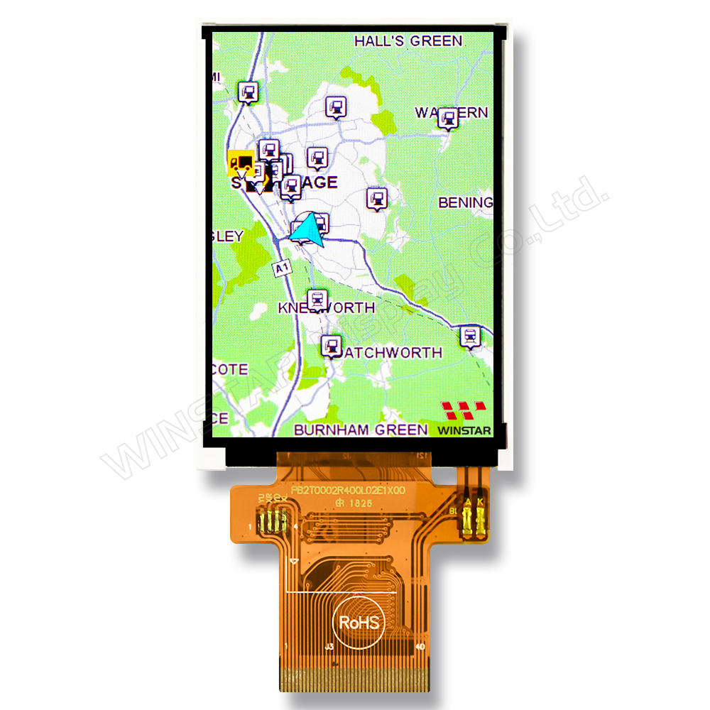
2.4-inch 240x320 High Brightness IPS TFT Display (Portrait Mode)

Model No. WF24LSYAJDNN0

►Size: 2.4"
►Resolution: 240×320 dots
►View Direction: IPS
►Interface: MCU, SPI
►Controller IC:ILI9341V
►Control-Board: No
►Brightness(cd/m²): 1000
►Frame Through Hole: No
►Touch Screen: Without Touch Screen

Description

The WF24LSYAJDNN0 is a 2.4-inch portrait IPS TFT display module with 240x320 resolution, offering 1000 nits high brightness for excellent readability in strong ambient light. With 80° wide viewing angles in all directions and a contrast ratio of 800:1, it ensures vibrant and consistent visuals. This module supports both MCU and SPI interfaces and is driven by the widely-used ILI9341V IC, making it easy to integrate into most systems. Its robust operating temperature range and LED lifetime of over 30,000 hours make it ideal for vertically oriented applications such as handheld instruments, medical devices, and outdoor control panels.

DRAWING

2.4-inch 240x320 High Brightness IPS TFT Display (Portrait Mode) - WF24LSYAJDNN0

SPECIFICATIONS

General Specifications

Item Dimension Unit
Size 2.4 inch
Dot Matrix 240 × RGB × 320(TFT) dots
Module dimension 42.72(W) × 60.26(H) × 2.8(D) mm
Active area 36.72 × 48.96 mm
Pixel Pitch 0.153 × 0.153 mm
LCD type TFT, Normally Black, Transmissive
Driver IC ILI9341V or equivalent
Viewing angle 80/80/80/80
Aspect Ratio Portrait
Backlight Type LED, Normally White
Touch Panel Without Touch Panel
Surface Glare

Absolute Maximum Ratings

Item Symbol Min Typ Max Unit
Operating Temperature TOP -20 +70
Storage Temperature TST -30 +80

Electrical Characteristics

Operating conditions

Item Symbol Min Typ Max Unit
Supply Voltage For Analog VCI 2.5 3.3 V
Supply Voltage For Logic IOVCC 2.5 3.3 V
Supply Current For LCM ICC 6 9 mA
 

LED driving conditions

Parameter Symbol Min. Typ. Max. Unit
LED current 40 mA
LED voltage VBL+ 10.8 11.6 12.4 V
LED Life Time 30,000 Hr

Interface Pin Function

NO Symbol Function I/O
1 GND Ground P
2-6 NC No connection -
7 VCI High voltage power supply for analog circuit blocks
(2.5 ~ 3.3 V)
P
8 IOVCC Low voltage power supply for interface logic circuits
(2.5 ~ 3.3 V)
P
9 TE Tearing effect output pin to synchronize MPU to frame writing, activated by S/W command. When this pin is not activated, this pin is low.
If not used, open this pin.
O
10 CS Chip select signal. I
11 D/CX(SCL) (D/CX): This pin is used to select “Data or Command” in the parallel interface.
When DCX = 1, data is selected.
When DCX = 0, command is selected.
(SCL): This pin is used as the serial interface clock in 3-wire
9-bit/4-wire 8-bit serial data interface.
If not used, this pin should be connected to IOVCC or GND.
I
12 WR(SPI_D/C) (WRX) - 8080-Ⅰ/8080-Ⅱ system: Serves as a write signal and writes data at the rising edge.
(D/CX) - 4-line system: Serves as the selector of command or parameter.
Fix to IOVCC level when not in use.
I
13 RD 8080-Ⅰ/8080-Ⅱ system (RDX): Serves as a read signal and MCU read data at the rising edge.
Fix to IOVCC level when not in use.
I
14-29 DB0~DB15 18-bit parallel bi-directional data bus for MCU system.
Fix to GND level when not in use.
I/O
30 RESET This signal will reset the device and must be applied to properly initialize the chip.
Signal is active low.
I
31 IM0 Select the MCU interface mode
IM2 IM1 IM0 MCU-Interface Mode DB Pin in use
Register/Content GRAM
0 0 0 80 MCU 8-bit bus
interface I
D[7:0] D[7:0]
0 0 1 80 MCU 16-bit bus
interface I
D[7:0] D[15:0]
0 1 0 80 MCU 9-bit bus
interface I
D[7:0] D[8:0]
0 1 1 80 MCU 18-bit bus
interface I
D[7:0] D[17:0]
1 0 1 3-wire 9-bit data serial
interface I
SDA: In/OUT
1 1 0 4-wire 8-bit data serial
interface I
SDA: In/OUT
MPU Parallel interface bus and serial interface select
If use RGB Interface must select serial interface.
* : Fix this pin at IOVCC or GND.
I
32 IM1
33 IM2
34 DB16 18-bit parallel bi-directional data bus for MCU system and RGB
interface mode
Fix to GND level when not in use.
I/O
35 DB17
36 VLED- Cathode of LED backlight. P
37 VLED- Cathode of LED backlight. P
38 VLED+ Anode of LED backlight. P
39 SDA SDA : Serial in/out signal.
The data is applied on the rising edge of the SCL signal.
If not used, fix this pin at IOVCC or GND.
I/O
40 NC Not used, open this pin N

Related Products

go top
close

We value your privacy

By clicking "Allow All Cookies", you agree to the storing of cookies on your device to enhance site navigation, analyse site usage, and assist in our marketing and performance efforts. You can find further information this subject in our policy.

We value your privacy

Winstar and certain third parties use cookies on www.winstar.com.tw. The details regarding the types of
cookies, their purpose and the third parties involved are described below and in our Cookie Policy.
Please click on “Allow All” to consent to our usage of cookies in order to have the best possible
experience on our websites. You can also set your preferences or reject cookies (except for strictly
necessary cookies).

Manage Consent Preferences

Always Active
Essential Cookies

These cookies are essential in order to enable you to move around the website and use its
features, such as setting your privacy preferences, logging in or filling in forms.

Analytics Cookies

Also known as “statistics cookies,” these cookies collect information about how you use a website, like which pages you visited and which links you clicked on. See Detail