На главную страницу Продукция OLED Дисплей Символьный OLED дисплей WEA002002A

20 символов x 2 линии COG OLED дисплеи +PCB

Артикул. WEA002002A

►Тип: Символьный
►Тип монтажа контроллера: COG+PCB
►20 символов x 2 линии
►IC:SSD1311
►3.3V Power supply
►1/16 duty
►Интерфейс: 6800, 8080, SPI, I2C
►Цвет дисплея: Белый / Желтый

Описание

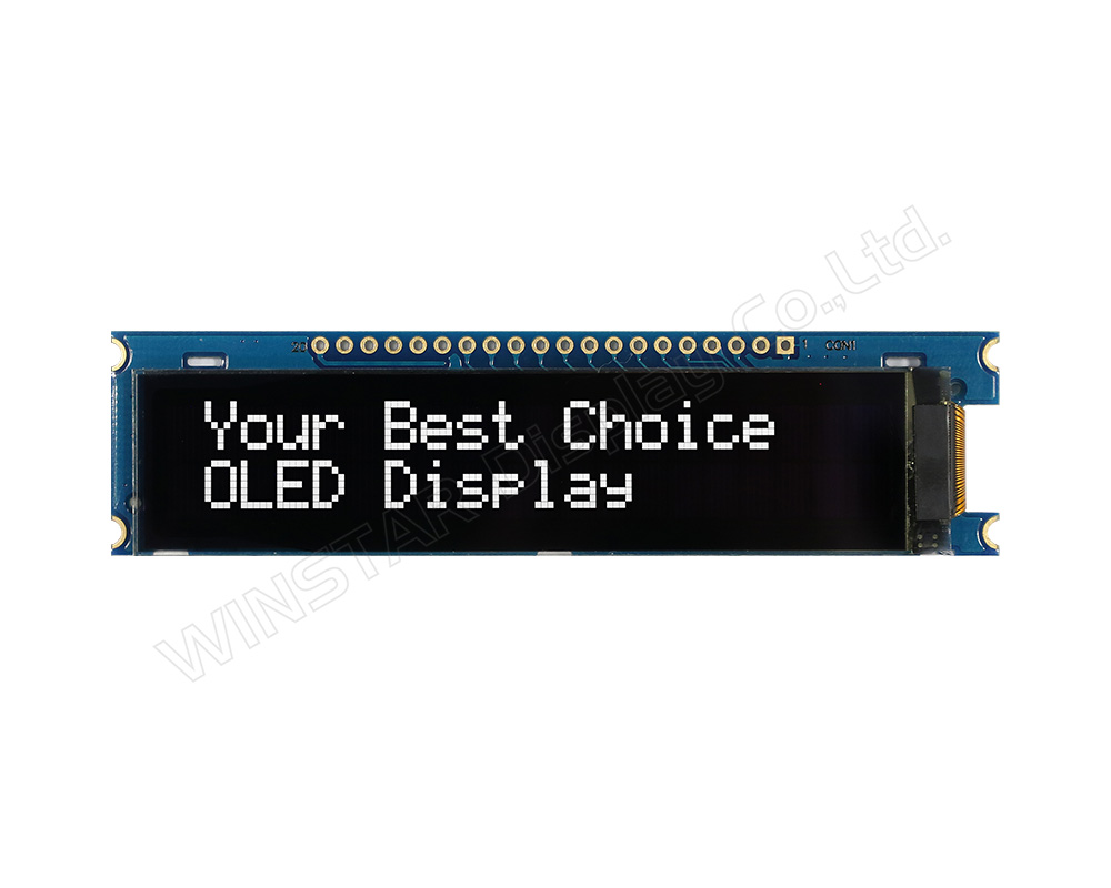
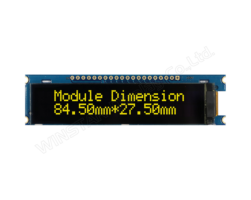
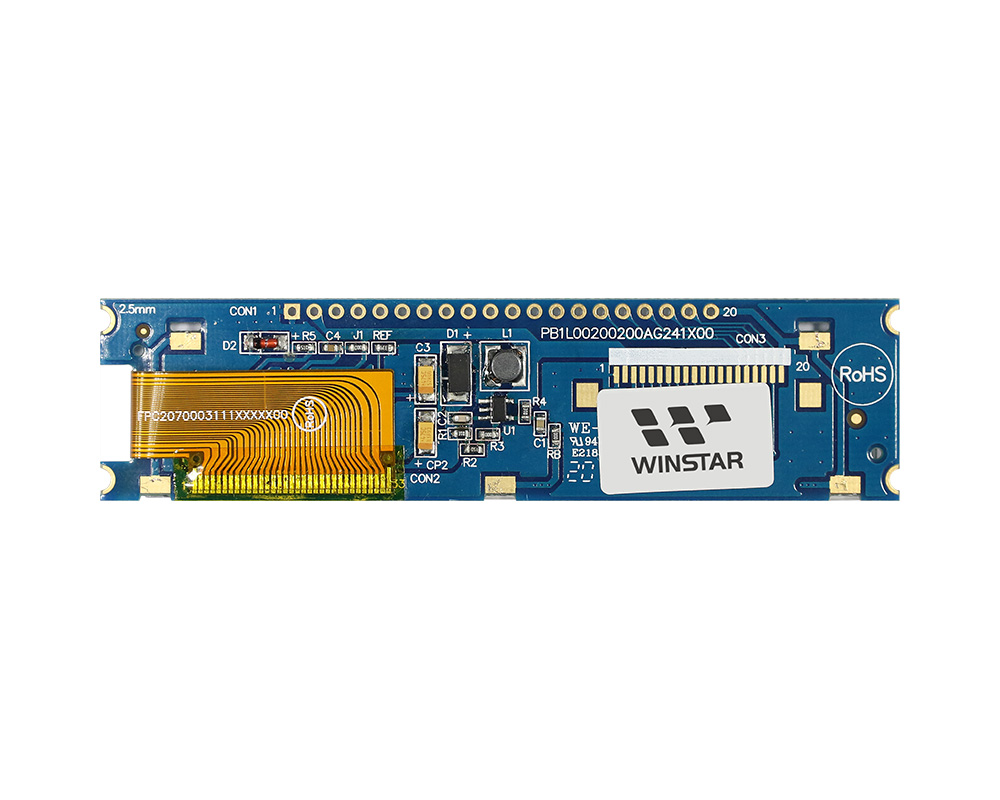
WEA002002A – это COG OLED модуль с печатной платой; диагональ модуля 2.93” 20 x 2 символа. Дисплей WEA002002A сделан на базе контроллера IC SSD1311 c поддержкой интерфейсов: параллельного 6800/8080 4/8-Бит, 4-х жильного SPI интерфейса и I2C интерфейса. Напряжение питания 3V (на выбор доступна модель 5V), 1/16 рабочий цикл. Модель оснащена встроенным контроллером шрифтов, который предлагает 4 набора шрифтов на одном устройстве: Английский/Японский, Западноевропейский, Скандинавско-европейский и Кириллица. Дизайн печатной платы WEA002002A подходит для клиентов, использующих кабельное соединение; так же не нужно самостоятельно разрабатывать дополнительно печатную плату. В данный OLED модуль интегрированы настройки интерфейса и схема VCC, которая упрощает использование индикатора.

OLED дисплей WEA002002A идеально подходит для применения в таких областях как: “умный дом”, POS системы, Облачных/IoT системах, умных устройствах, автомобилестроении, коммуникационных системах, медицинских устройствах и т.д. WEA002002A может работать при температурах от -40°С до +80°С; а температура хранения - от -40°С до +85°С.

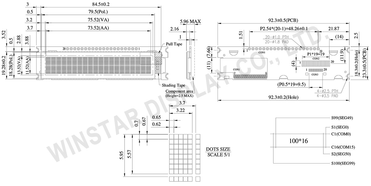
Чертеж

20 Characters x 2 Lines COG OLED Display with PCB - WEA002002A

Технические характеристики

Функции контроллера контактного интерфейса

Pin No. 기호 Pin Type 기능
1 VSS P Ground pin. It must be connected to external ground.
2 VDD P Power supply for core logic operation.
A capacitor should be connected between VDD and VSS under all circumstances.
3 REGVDD I Internal VDD regulator selection pin
It must be connected to external ground.
4 D/C# I This pin is Data/Command control pin connecting to the MCU.
When the pin is pulled HIGH, the data at D[7:0] will be interpreted as data.
When the pin is pulled LOW, the data at D[7:0] will be transferred to a command register.
In I2C mode, this pin acts as SA0 for slave address selection.
When serial interface is selected, this pin must be connected to VSS.
5 R/W# I This pin is read / write control input pin connecting to the MCU interface.
When 6800 interface mode is selected, this pin will be used as Read/Write (R/W#) selection input. Read mode will be carried out when this pin is pulled HIGH and write mode when LOW.
When 8080 interface mode is selected, this pin will be the Write (WR#) input. Data write operation is initiated when this pin is pulled LOW and the chip is selected.
When serial or I2C interface is selected, this pin must be connected to VSS.
6 E I This pin is MCU interface input.
When 6800 interface mode is selected, this pin will be used as the Enable (E) signal.
Read/write operation is initiated when this pin is pulled HIGH and the chip is selected.
When 8080 interface mode is selected, this pin receives the Read (RD#) signal. Read operation is initiated when this pin is pulled LOW and the chip is selected.
When serial or I2C interface is selected, this pin must be connected to VSS.
7 D0 I/O These pins are bi-directional data bus connecting to the MCU data bus. 
Unused pins are recommended to tie LOW.
When serial interface mode is selected, D0 will be the serial clock input: SCLK; D1 will be the serial data input: SID and D2 will be the serial data output: SOD.
When I2C mode is selected, D2, D1 should be tied together and serve as SDAout, SDAin in application and D0 is the serial clock input, SCL.
8 D1
9 D2
10 D3
11 D4
12 D5
13 D6
14 D7
15 CS# I This pin is the chip select input connecting to the MCU.  
The chip is enabled for MCU communication only when CS# is pulled LOW (active LOW).
In I2C mode, this pin must be connected to VSS.  
16 RES# I This pin is reset signal input.  
When the pin is pulled LOW, initialization of the chip is executed.
Keep this pin pull HIGH during normal operation.
17 BS0 I MCU bus interface selection pins. Select appropriate logic setting as described in the following table. BS2, BS1 and BS0 are pin select.
Bus Interface selection
BS[2:0] Interface
000 Serial Interface
001 Invalid
010 I2C
011 Invalid
100 8-bit 6800 parallel
101 4-bit 6800 parallel
110 8-bit 8080 parallel
111 4-bit 8080 parallel
Note
(1) 0 is connected to VSS
(2) 1 is connected to VDD
18 BS1
19 BS2
20 VSS P Ground pin. It must be connected to external ground.

Механические характеристики

Наименование Измерения Единица
количество символов 20 символов x 2 линии
Габариты 92.3 x 23.3 x 5.96 Max. mm
Активная область 73.52 x 11.52 mm
Размер пикселя 0.62 x 0.67 mm
Шаг пикселя 0.65 x 0.70 mm
Размер символов 3.22 x 5.57 mm
шаг расположения символов 3.70 x 5.95 mm
Тип LCD OLED , монохромные
Duty 1/16
IC SSD1311
Интерфейс 6800, 8080, SPI, I2C
Диагональ 2.93 дюйма

Абсолютные максимальные значения

Наименование Символы Минимальный Максимальный Единица
Supply Voltage For Logic VDD-VSS -0.3 3.6 V
Диапазон рабочих температур TOP -40 +80 °C
Температура хранения TST -40 +85 °C
 

Электронные характеристики

DC Электронные характеристики

Наименование Символы Кондиция Минимальный Типичный Максимальный Единица
Напряжение питания логических схем VDD-VSS 3.1 3.3 3.5 V
Высокое входное напряжение VIH 0.8xVDD V
Низкое входное напряжение VIL 0.2xVDD V
Высокое напряжение на выходе VOH IOH=-0.5mA 0.9xVDD V
Низкое напряжение на выходе VOL IOL=0.5mA 0.1xVDD V
50% Check Board
Operating Current
IDD VDD=3.3V 50 75 mA
 

Search keyword: oled 20x2, 20x2 oled

go top
close