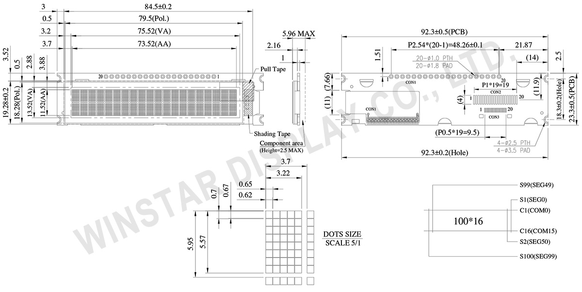
Ana sayfa Ürünler OLED Ekran Karakter OLED Ekran WEA002002A

20 karakter x 2 satır COG OLED Ekran +PCB

Model No. WEA002002A

►Türü : Karakter
►Yapı : COG+PCB
►20 karakter x 2 satır
►IC:SSD1311
►3.3V güç sağlayıcı
►1/16 görev
►Ara yüz: 6800, 8080, SPI, I2C
►OLED Rengi: Beyaz / Sarı

ÇIZIM

20 Characters x 2 Lines COG OLED Display with PCB - WEA002002A

AYRINTILAR

Arayüz Pin Fonksiyonlari

Pin No. Sembol Pin Type TANIM
1 VSS P Ground pin. It must be connected to external ground.
2 VDD P Power supply for core logic operation.
A capacitor should be connected between VDD and VSS under all circumstances.
3 REGVDD I Internal VDD regulator selection pin
It must be connected to external ground.
4 D/C# I This pin is Data/Command control pin connecting to the MCU.
When the pin is pulled HIGH, the data at D[7:0] will be interpreted as data.
When the pin is pulled LOW, the data at D[7:0] will be transferred to a command register.
In I2C mode, this pin acts as SA0 for slave address selection.
When serial interface is selected, this pin must be connected to VSS.
5 R/W# I This pin is read / write control input pin connecting to the MCU interface.
When 6800 interface mode is selected, this pin will be used as Read/Write (R/W#) selection input. Read mode will be carried out when this pin is pulled HIGH and write mode when LOW.
When 8080 interface mode is selected, this pin will be the Write (WR#) input. Data write operation is initiated when this pin is pulled LOW and the chip is selected.
When serial or I2C interface is selected, this pin must be connected to VSS.
6 E I This pin is MCU interface input.
When 6800 interface mode is selected, this pin will be used as the Enable (E) signal.
Read/write operation is initiated when this pin is pulled HIGH and the chip is selected.
When 8080 interface mode is selected, this pin receives the Read (RD#) signal. Read operation is initiated when this pin is pulled LOW and the chip is selected.
When serial or I2C interface is selected, this pin must be connected to VSS.
7 D0 I/O These pins are bi-directional data bus connecting to the MCU data bus. 
Unused pins are recommended to tie LOW.
When serial interface mode is selected, D0 will be the serial clock input: SCLK; D1 will be the serial data input: SID and D2 will be the serial data output: SOD.
When I2C mode is selected, D2, D1 should be tied together and serve as SDAout, SDAin in application and D0 is the serial clock input, SCL.
8 D1
9 D2
10 D3
11 D4
12 D5
13 D6
14 D7
15 CS# I This pin is the chip select input connecting to the MCU.  
The chip is enabled for MCU communication only when CS# is pulled LOW (active LOW).
In I2C mode, this pin must be connected to VSS.  
16 RES# I This pin is reset signal input.  
When the pin is pulled LOW, initialization of the chip is executed.
Keep this pin pull HIGH during normal operation.
17 BS0 I MCU bus interface selection pins. Select appropriate logic setting as described in the following table. BS2, BS1 and BS0 are pin select.
Bus Interface selection
BS[2:0] Interface
000 Serial Interface
001 Invalid
010 I2C
011 Invalid
100 8-bit 6800 parallel
101 4-bit 6800 parallel
110 8-bit 8080 parallel
111 4-bit 8080 parallel
Note
(1) 0 is connected to VSS
(2) 1 is connected to VDD
18 BS1
19 BS2
20 VSS P Ground pin. It must be connected to external ground.

Mekanik Veri

Kalem Ölçü Birim
Ekran Formati 20 karakter x 2 satır
Modül ölçüleri 92.3 x 23.3 x 5.96 Max. mm
Aktif alan 73.52 x 11.52 mm
Nokta boyutu 0.62 x 0.67 mm
Nokta sıklığı 0.65 x 0.70 mm
Karakter Boyutu 3.22 x 5.57 mm
Character pitch 3.70 x 5.95 mm
LCD Tipi OLED , monokrom
Duty 1/16
IC SSD1311
Arayüz 6800, 8080, SPI, I2C
Boyut (Köşegen) 2.93 inç

Maksimum Değerler

Kalem Symbol Minumum Deger Maksimum Deger Birim
Supply Voltage For Logic VDD-VSS -0.3 3.6 V
Çalışma Sıcaklığı TOP -40 +80 °C
Saklama Sıcaklığı TST -40 +85 °C
 

Elektronik Özellikleri

DC Elektronik Özellikleri

Kalem Sembol Durum Minumum Deger Tipik Deger Maksimum Deger Birim
Supply Voltage For Logic VDD-VSS 3.1 3.3 3.5 V
Input High Volt. VIH 0.8xVDD V
Input Low Volt. VIL 0.2xVDD V
Output High Volt. VOH IOH=-0.5mA 0.9xVDD V
Output Low Volt. VOL IOL=0.5mA 0.1xVDD V
50% Check Board
Operating Current
IDD VDD=3.3V 50 75 mA
 

Search keyword: oled 20x2, 20x2 oled

go top
close