私たちはあなたのプライバシーを大切にします
「すべてのクッキーを許可」をクリックすると、サイトのナビゲーションを向上させ、サイト使用状況を分析し、マーケティングおよびパフォーマンスの取り組みを支援するために、クッキーをデバイスに保存することに同意したことになります。この件に関する詳細情報は、ポリシーをご覧ください。プライバシーポリシー

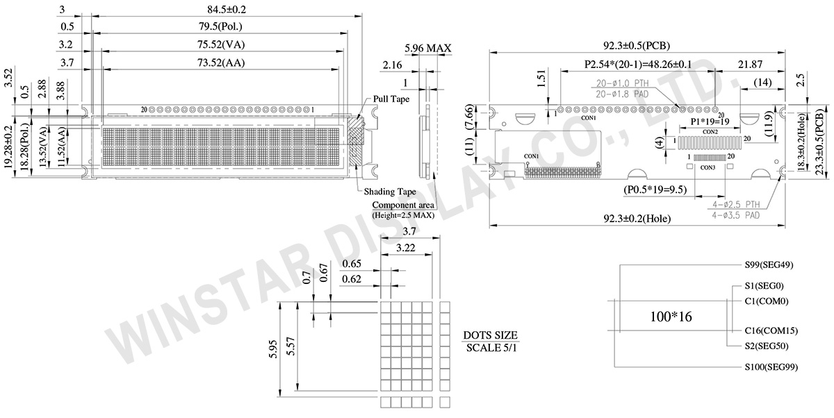
WEA002002AモデルはモジュールにPCBを備えた2.93インチ20文字×2行のCOG文字OLEDです。お客様のアプリケーションにとって、4つの取り付け穴を付きPCBは簡単に固定できる設計です。このモジュールはSSD1311ICに組み込まれて、6800(イニシャル仕様)/8080 4ビット/ 8ビットパラレル、I2C、及び4線式SPIシリアルインターフェースをサポートします。ASCII、英語、ヨーロッパ及び日本語の文字用のROMが有って、ロジックの供給電圧はデフォルトが3.3Vで、オプションが5Vです。WEA002002AシリーズのPCB設計は、お客様がケーブル接続を使用するのに適して、自分で追加のPCBを開発する必要はありません。このモジュールは、インターフェース設定とVCC回路を統合していることで、お客様は簡単に使用できます。
この2.93インチのキャラクターOLEDモジュールは、スマートホームアプリケーション、医療機器、スマートコントロール、産業用コントロール等に適しています。

Data source ref: WEA002002AWAP3N00000
| 項目 | サイズ | 単位 |
|---|---|---|
| 表示形式 | 20文字x2行 | - |
| モジュールサイズ | 92.3 x 23.3 x 5.96 Max. | mm |
| アクティブエリア | 73.52 x 11.52 | mm |
| ドットサイズ | 0.62 x 0.67 | mm |
| ドットピッチ | 0.65 x 0.70 | mm |
| 文字サイズ | 3.22 x 5.57 | mm |
| 文字ピッチ | 3.70 x 5.95 | mm |
| LCDタイプ | OLED , モノクロ | |
| Duty | 1/16 | |
| IC | SSD1311 | |
| インターフェイス | 6800, 8080, SPI, I2C | |
| サイズ | 2.93 インチ | |
| 項目 | 記号 | 最小値 | 最大値 | 単位 |
|---|---|---|---|---|
| ロジック電源電圧 | VDD-VSS | -0.3 | 3.6 | V |
| 操作温度 | TOP | -40 | +80 | °C |
| 保存温度 | TST | -40 | +85 | °C |
| 項目 | 記号 | 条件 | 最小値 | 典型値 | 最大値 | 単位 |
|---|---|---|---|---|---|---|
| ロジック電源電圧 | VDD-VSS | - | 3.1 | 3.3 | 3.5 | V |
| 高レベル入力電圧 | VIH | - | 0.8xVDD | - | - | V |
| 低レベル入力電圧 | VIL | - | - | - | 0.2xVDD | V |
| 高レベル出力電圧 | VOH | IOH=-0.5mA | 0.9xVDD | - | - | V |
| 低レベル出力電圧 | VOL | IOL=0.5mA | - | - | 0.1xVDD | V |
| 50% Check Board Operating Current |
IDD | VDD=3.3V | - | 50 | 75 | mA |
| Pin No. | 記号 | Pin Type | 説明 | ||||||||||||||||||
|---|---|---|---|---|---|---|---|---|---|---|---|---|---|---|---|---|---|---|---|---|---|
| 1 | VSS | P | Ground pin. It must be connected to external ground. | ||||||||||||||||||
| 2 | VDD | P | Power supply for core logic operation. A capacitor should be connected between VDD and VSS under all circumstances. |
||||||||||||||||||
| 3 | REGVDD | I | Internal VDD regulator selection pin It must be connected to external ground. |
||||||||||||||||||
| 4 | D/C# | I | This pin is Data/Command control pin connecting to the MCU. When the pin is pulled HIGH, the data at D[7:0] will be interpreted as data. When the pin is pulled LOW, the data at D[7:0] will be transferred to a command register. In I2C mode, this pin acts as SA0 for slave address selection. When serial interface is selected, this pin must be connected to VSS. |
||||||||||||||||||
| 5 | R/W# | I | This pin is read / write control input pin connecting to the MCU interface. When 6800 interface mode is selected, this pin will be used as Read/Write (R/W#) selection input. Read mode will be carried out when this pin is pulled HIGH and write mode when LOW. When 8080 interface mode is selected, this pin will be the Write (WR#) input. Data write operation is initiated when this pin is pulled LOW and the chip is selected. When serial or I2C interface is selected, this pin must be connected to VSS. |
||||||||||||||||||
| 6 | E | I | This pin is MCU interface input. When 6800 interface mode is selected, this pin will be used as the Enable (E) signal. Read/write operation is initiated when this pin is pulled HIGH and the chip is selected. When 8080 interface mode is selected, this pin receives the Read (RD#) signal. Read operation is initiated when this pin is pulled LOW and the chip is selected. When serial or I2C interface is selected, this pin must be connected to VSS. |
||||||||||||||||||
| 7 | D0 | I/O | These pins are bi-directional data bus connecting to the MCU data bus. Unused pins are recommended to tie LOW. When serial interface mode is selected, D0 will be the serial clock input: SCLK; D1 will be the serial data input: SID and D2 will be the serial data output: SOD. When I2C mode is selected, D2, D1 should be tied together and serve as SDAout, SDAin in application and D0 is the serial clock input, SCL. |
||||||||||||||||||
| 8 | D1 | ||||||||||||||||||||
| 9 | D2 | ||||||||||||||||||||
| 10 | D3 | ||||||||||||||||||||
| 11 | D4 | ||||||||||||||||||||
| 12 | D5 | ||||||||||||||||||||
| 13 | D6 | ||||||||||||||||||||
| 14 | D7 | ||||||||||||||||||||
| 15 | CS# | I | This pin is the chip select input connecting to the MCU. The chip is enabled for MCU communication only when CS# is pulled LOW (active LOW). In I2C mode, this pin must be connected to VSS. |
||||||||||||||||||
| 16 | RES# | I | This pin is reset signal input. When the pin is pulled LOW, initialization of the chip is executed. Keep this pin pull HIGH during normal operation. |
||||||||||||||||||
| 17 | BS0 | I | MCU bus interface selection pins. Select appropriate logic setting as described in the following table. BS2, BS1 and BS0 are pin select. Bus Interface selection
(1) 0 is connected to VSS (2) 1 is connected to VDD |
||||||||||||||||||
| 18 | BS1 | ||||||||||||||||||||
| 19 | BS2 | ||||||||||||||||||||
| 20 | VSS | P | Ground pin. It must be connected to external ground. |
Search keyword: oled 20x2, 20x2 oled
「すべてのクッキーを許可」をクリックすると、サイトのナビゲーションを向上させ、サイト使用状況を分析し、マーケティングおよびパフォーマンスの取り組みを支援するために、クッキーをデバイスに保存することに同意したことになります。この件に関する詳細情報は、ポリシーをご覧ください。プライバシーポリシー