Startseite Produkte OLED-Anzeige Zeichen-OLED-Anzeigen WEA002002A

20 Zeichen × 2 Zeilen COG OLED-Display-Modul +PCB

Modellnummer WEA002002A

►Typ: Zeichen
►Bauweise: COG+PCB
►20 Zeichen × 2 Zeilen
►IC:SSD1311
►3,3-V-Stromversorgung
►1/16 duty
►Schnittstelle: 6800, 8080, SPI, I2C
►die Farbe des Displays: Weiß / Gelb

Beschreibung

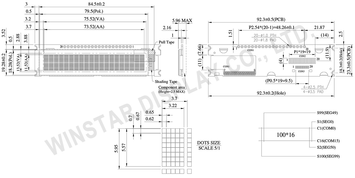
Das Modell WEA002002A ist ein 2,93 Zoll COG OLED-Anzeigemodul mit einer integrierten PCB. Es bietet ein Display im Format 2x20 Zeichen und kommt mit einer PCB, die vier Befestigungslöcher enthält, um die Installation in verschiedenen Anwendungen zu erleichtern. Die Abmessungen des Moduls betragen 92,3 x 23,3 mm bei einer Dicke von 5,96 mm. Der aktive Bereich misst 73,52 x 11,52 mm.

Das Modul ist mit einem SSD1311 IC ausgestattet und unterstützt die Schnittstellen 6800/8080 4-Bit/8-Bit parallel, I2C und 4-Draht SPI. Es enthält ROMs für ASCII, englische, europäische und japanische Zeichen. Die Standard-Betriebsspannung für die Logik beträgt 3,3 V, optional sind auch 5 V verfügbar. Der Display-Stromverbrauch beträgt 50 mA bei 3,3 VDD (typischer Wert) mit einer 50%-Überprüfung des Board-Stroms und arbeitet mit einer Treiberpflicht von 1/16.

Das WEA002002A COG OLED-Anzeigemodul ist eine verbesserte Version des WEO002002A Modells und bietet zusätzlich eine PCB-Platine. Das PCB-Design des WEA002002A ist für Kabelverbindungen geeignet, was es den Kunden erleichtert, die PCB nicht selbst entwickeln zu müssen. Dieses Modul integriert die Schnittstelleneinstellungen und die VCC-Schaltung, was die Verwendung vereinfacht.

Dieses 2,93 Zoll große OLED-Modul eignet sich ideal für Anwendungen in Smart-Home-Systemen, medizinischen Geräten, intelligenten Steuerungen, industriellen Steuerungen und mehr. Das WEA002002A Modul kann bei Temperaturen von -40°C bis +80°C betrieben werden und bei Temperaturen von -40°C bis +85°C gelagert werden.

Zeichnung

20 Characters x 2 Lines COG OLED Display with PCB - WEA002002A

Data source ref: WEA002002AWAP3N00000

Technische Daten

Schnittstelle Pin-Funktion

Pin No. Symbol Pin Type Description
1 VSS P Ground pin. It must be connected to external ground.
2 VDD P Power supply for core logic operation.
A capacitor should be connected between VDD and VSS under all circumstances.
3 REGVDD I Internal VDD regulator selection pin
It must be connected to external ground.
4 D/C# I This pin is Data/Command control pin connecting to the MCU.
When the pin is pulled HIGH, the data at D[7:0] will be interpreted as data.
When the pin is pulled LOW, the data at D[7:0] will be transferred to a command register.
In I2C mode, this pin acts as SA0 for slave address selection.
When serial interface is selected, this pin must be connected to VSS.
5 R/W# I This pin is read / write control input pin connecting to the MCU interface.
When 6800 interface mode is selected, this pin will be used as Read/Write (R/W#) selection input. Read mode will be carried out when this pin is pulled HIGH and write mode when LOW.
When 8080 interface mode is selected, this pin will be the Write (WR#) input. Data write operation is initiated when this pin is pulled LOW and the chip is selected.
When serial or I2C interface is selected, this pin must be connected to VSS.
6 E I This pin is MCU interface input.
When 6800 interface mode is selected, this pin will be used as the Enable (E) signal.
Read/write operation is initiated when this pin is pulled HIGH and the chip is selected.
When 8080 interface mode is selected, this pin receives the Read (RD#) signal. Read operation is initiated when this pin is pulled LOW and the chip is selected.
When serial or I2C interface is selected, this pin must be connected to VSS.
7 D0 I/O These pins are bi-directional data bus connecting to the MCU data bus. 
Unused pins are recommended to tie LOW.
When serial interface mode is selected, D0 will be the serial clock input: SCLK; D1 will be the serial data input: SID and D2 will be the serial data output: SOD.
When I2C mode is selected, D2, D1 should be tied together and serve as SDAout, SDAin in application and D0 is the serial clock input, SCL.
8 D1
9 D2
10 D3
11 D4
12 D5
13 D6
14 D7
15 CS# I This pin is the chip select input connecting to the MCU.  
The chip is enabled for MCU communication only when CS# is pulled LOW (active LOW).
In I2C mode, this pin must be connected to VSS.  
16 RES# I This pin is reset signal input.  
When the pin is pulled LOW, initialization of the chip is executed.
Keep this pin pull HIGH during normal operation.
17 BS0 I MCU bus interface selection pins. Select appropriate logic setting as described in the following table. BS2, BS1 and BS0 are pin select.
Bus Interface selection
BS[2:0] Interface
000 Serial Interface
001 Invalid
010 I2C
011 Invalid
100 8-bit 6800 parallel
101 4-bit 6800 parallel
110 8-bit 8080 parallel
111 4-bit 8080 parallel
Note
(1) 0 is connected to VSS
(2) 1 is connected to VDD
18 BS1
19 BS2
20 VSS P Ground pin. It must be connected to external ground.

mechanische Daten

Artikel Ausmaß Einheit
Anzeigeformat 20 Zeichen × 2 Zeilen
Abmaße der modul 92,3 x 23,3 x 5,96 Max. mm
Aktiver Bereich 73,52 x 11,52 mm
Punktgröße 0,62 x 0,67 mm
Punktabstand 0,65 x 0,70 mm
Zeichengröße 3,22 x 5,57 mm
Character pitch 3,70 x 5,95 mm
LCD-Typ OLED, Monochrome
Duty 1/16
IC SSD1311
Schnittstelle 6800, 8080, SPI, I2C
Größe (Diagonale) 2,93 Zoll

Absolute Grenzwerte

Artikel Symbol Mindestwert Maximalwert Einheit
Supply Voltage For Logic VDD-VSS -0,3 3,6 V
Betriebstemperatur TOP -40 +80 °C
Lagertemperatur TST -40 +85 °C
 

elektronische Eingenschaften

DC elektronische Eingenschaften

Artikel Symbol Bedingung Mindestwert typischer Wert Maximalwert Einheit
Supply Voltage For Logic VDD-VSS 3,1 3,3 3,5 V
Input High Volt. VIH 0,8xVDD V
Input Low Volt. VIL 0,2xVDD V
Output High Volt. VOH IOH=-0,5mA 0,9xVDD V
Output Low Volt. VOL IOL=0,5mA 0,1xVDD V
50% Check Board
Operating Current
IDD VDD=3,3V 50 75 mA

Ähnliche Produkte

go top
close

Wir schätzen Ihre Privatsphäre

Durch Klicken auf „Alle Cookies zulassen“ stimmen Sie der Speicherung von Cookies auf Ihrem Gerät zu, um die Navigation auf der Website zu verbessern, die Nutzung der Website zu analysieren und unsere Marketing- und Leistungsbemühungen zu unterstützen. Weitere Informationen zu diesem Thema finden Sie in unserer Richtlinie. Datenschutzrichtlinie

Wir schätzen Ihre Privatsphäre

Winstar und bestimmte Drittparteien verwenden Cookies auf www.winstar.com.tw. Die Einzelheiten zu den Arten von Cookies, ihrem Zweck und den beteiligten Drittparteien sind unten sowie in unserer Cookie-Richtlinie beschrieben. Klicken Sie auf „Alle zulassen“, um unserer Verwendung von Cookies zuzustimmen und die bestmögliche Erfahrung auf unseren Websites zu erzielen. Sie können auch Ihre Präferenzen festlegen oder Cookies ablehnen (mit Ausnahme der unbedingt erforderlichen Cookies).

Einwilligungspräferenzen verwalten

Immer aktiv
Notwendige Cookies

Diese Cookies sind unerlässlich, um Ihnen das Navigieren auf der Website zu ermöglichen und ihre Funktionen zu nutzen, wie z. B. das Festlegen Ihrer Datenschutzpräferenzen, das Einloggen oder das Ausfüllen von Formularen.

Analyse-Cookies

Diese Cookies, auch als „Statistik-Cookies“ bekannt, sammeln Informationen darüber, wie Sie eine Website nutzen, z. B. welche Seiten Sie besucht und auf welche Links Sie geklickt haben. Siehe Details.