WF101JTYAHLNT0 is a 10.1-inch landscape mode IPS TFT LCD module featuring a resistive touch screen TFT, offering a resolution of 1024x600 pixels. This model is built with EK79001HN and EK73215BCGA driver ICs, supporting an LVDS interface. It provides a contrast ratio of 800:1 (typical value), a brightness of 350 nits (typical value), a 16:9 aspect ratio, and an anti-glare surface glass with a normally black, transmissive LCD type.
Thanks to IPS technology, this module offers superior color reproduction, wide viewing angles, and consistent image quality, making it ideal for applications where clarity and detail are essential. Compared to TN TFT displays, the 10.1-inch IPS TFT provides a significantly wider viewing angle of Left: 85 / Right: 85 / Up: 85 / Down: 85 degrees (typical value), ensuring excellent color consistency and visibility from different angles. The anti-glare surface further enhances readability in bright lighting conditions, reducing reflections and improving visibility.
Wide Application Range
The TFT resistive touchscreen WF101JTYAHLNT0 is ideal for indoor industrial and commercial applications, including human-machine interfaces (HMI), medical equipment, office automation systems, self-service kiosks, and control panels. With its IPS technology and anti-glare surface, it delivers consistent colors and wide viewing angles, making it perfect for applications where clarity and readability are essential.
Resistive Touch Panel Advantages
Equipped with a TFT resistive touch panel, this display module allows for precise touch input using a stylus, gloved hands, or even objects like plastic pens. This makes it an excellent choice for industrial and medical applications where users may wear gloves or require high-accuracy touch input. Unlike capacitive touch panels, resistive touch screens are less affected by water or contaminants on the surface, ensuring reliable operation in demanding environments. With their robust structure, resistive touch screen TFTs provide excellent durability while maintaining reliable operation in various environmental conditions.
The power supply voltage (VDD) of the WF101JTYAHLNT0 ranges from 3.0V to 3.6V, with a typical value of 3.3V. It operates at temperatures from -20℃ to +70℃ and can be stored at temperatures ranging from -30℃ to +80℃, ensuring reliable performance in various environmental conditions.
SPECIFICATIONS
General Specifications
| Item |
Dimension |
Unit |
| Size |
10.1 |
inch |
| Dot Matrix |
1024 RGB x 600 |
dots |
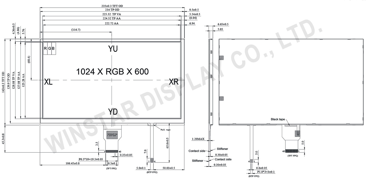
| Module dimension |
235(W) x 143(H) x 6.65(D) |
mm |
| Active area |
222.72 (H) x 125.28(V) |
mm |
| Dot pitch |
0.2175(W) x 0.2088(H) |
mm |
| LCD type |
TFT, Normally Black, Transmissive |
| Interface |
LVDS |
| Driver IC |
EK79001HN + EK73215BCGA or equivalent |
| Viewing Angle |
85/85/85/85 |
| Aspect Ratio |
16:9 |
| Backlight Type |
LED, Normally White |
| Touch Panel |
Resistive Touch Panel |
| Surface |
Anti-Glare |
Absolute Maximum Ratings
| Item |
Symbol |
Min |
Typ |
Max |
Unit |
| Operating Temperature |
TOP |
-20 |
- |
+70 |
℃ |
| Storage Temperature |
TST |
-30 |
- |
+80 |
℃ |
Electrical Characteristics
Typical Operation Conditions (At Ta = 25 °C,)
| Item |
Symbol |
Min |
Typ |
Max |
Unit |
| Digital Power Supply Voltage For LCD |
VDD |
3 |
3.3 |
3.6 |
V |
| Analog Power Supply Voltage |
AVDD |
9.89 |
10.2 |
10.5 |
V |
| Gate On Power Supply Voltage |
VGH |
19.4 |
20.0 |
20.6 |
V |
| Gate Off Power Supply Voltage |
VGL |
-10.3 |
-10.0 |
-9.7 |
V |
| Common Power Supply Voltage |
VCOM |
4.0 |
4.3 |
4.6 |
V |
| Input logic high voltage |
VIH |
0.7 VDD |
- |
VDD |
V |
| Input logic low voltage |
VIL |
0 |
- |
0.3 VDD |
V |
Interface
TFT LCD Module
| Pin No. |
Symbol |
Description |
| 1 |
VCOM |
Common voltage |
| 2 |
VDD |
Digital power |
| 3 |
VDD |
Digital power |
| 4 |
NC |
Not connect |
| 5 |
Reset |
Global reset pin. Active low to enter reset state. Suggest to connecting with an RC reset circuit for stability. Normally pull high. (R=10KΩ,C=1μF) |
| 6 |
STBYB |
Standby mode, normally pull high STBYB=”1”, normal operation STBYB=”0”,timing control, source driver will turn off, all output are high-Z |
| 7 |
GND |
Digital ground |
| 8 |
RXIN0- |
Negative LVDS differential data inputs |
| 9 |
RXIN0+ |
Positive LVDS differential data inputs |
| 10 |
GND |
Digital ground |
| 11 |
RXIN1- |
Negative LVDS differential data inputs |
| 12 |
RXIN1+ |
Positive LVDS differential data inputs |
| 13 |
GND |
Digital ground |
| 14 |
RXIN2- |
Negative LVDS differential data inputs |
| 15 |
RXIN2+ |
Positive LVDS differential data inputs |
| 16 |
GND |
Digital ground |
| 17 |
RXCLKN- |
Negative LVDS differential clock inputs |
| 18 |
RXCLKN+ |
Positive LVDS differential clock inputs |
| 19 |
GND |
Digital ground |
| 20 |
RXIN3- |
Negative LVDS differential data inputs |
| 21 |
RXIN3+ |
Positive LVDS differential data inputs |
| 22 |
GND |
Digital ground |
| 23 |
NC |
Not connect |
| 24 |
NC |
Not connect |
| 25 |
GND |
Digital ground |
| 26 |
NC |
Not connect |
| 27 |
NC |
Not connect |
| 28 |
SELB |
6-bit/8-bit input select SELB = L , 8-bit ; SELB = H , 6-bit |
| 29 |
AVDD |
Analog power |
| 30 |
GND |
Digital ground |
| 31 |
LED- |
LED Cathode |
| 32 |
LED- |
LED Cathode |
| 33 |
L/R |
Left or right display control |
| 34 |
U/D |
Up / down display control |
| 35 |
VGL |
Negative power for TFT |
| 36 |
NC |
Not connect |
| 37 |
NC |
Not connect |
| 38 |
VGH |
Positive power for TFT |
| 39 |
LED+ |
LED Anode |
| 40 |
LED+ |
LED Anode |
When L/R="0",set right to left scan direction.
When L/R="1",set left to right scan direction.
When U/D="0",set top to bottom scan direction.
When U/D="1",set bottom to top scan direction.
resistive touch screen tft, tft resistive touch, tft resistive touchscreen, resistive touch screen


 - WG320240CX")
