The WF101JSYAHLNB0 is a high brightness 10.1-inch IPS TFT display module featuring a Projected Capacitive Touch Panel (PCAP), boasting a resolution of 1024x600 pixels. Equipped with the EK79001HN and EK73215BCGA driver ICs, it supports an LVDS interface and delivers exceptional performance with a contrast ratio of 800:1 (typical value) and a brightness of 900 nits (typical value). The display has a 16:9 aspect ratio, ensuring optimal viewing for multimedia applications.
Enhanced IPS Viewing Angle
The 10.1-inch IPS display offers superior color accuracy and a wider viewing angle compared to traditional TN panels. Its viewing angles are Left:85° / Right:85° / Up:85° / Down:85° (typical value), allowing for consistent and vivid visuals from virtually any angle. This makes it an ideal choice for interactive displays, industrial control systems, and other applications where clarity is crucial from all perspectives.
Projected Capacitive Touch Panel with 5-Point Touch
The Capacitive Touch Panel integrated into the WF101JSYAHLNB0 model features the ILI2511 IC, supporting 5-point multi-touch. This provides a highly responsive touch experience, making the display compatible with various operating systems including Windows, Linux, Android, and Mac. The module supports both USB and I2C interfaces, allowing for easy integration into a wide range of systems. For more details on the USB/I2C interface Capacitive Touch Screen with ILI2511 IC, please visit WINSTAR's technical article.
Operating Conditions
The WF101JSYAHLNB0 operates with a power supply voltage (VDD) ranging from 3.0V to 3.6V, with a typical value of 3.3V. It is designed to function in temperatures from -20℃ to +70℃ and can be stored in environments ranging from -30℃ to +80℃, making it suitable for various industrial and outdoor applications.
For customers who require a Resistive Touch Panel, the WF101JSYAHLNT0 model is available.
SPECIFICATIONS
General Specifications
| Item |
Dimension |
Unit |
| Size |
10.1 |
inch |
| Dot Matrix |
1024 RGB x 600 |
dots |
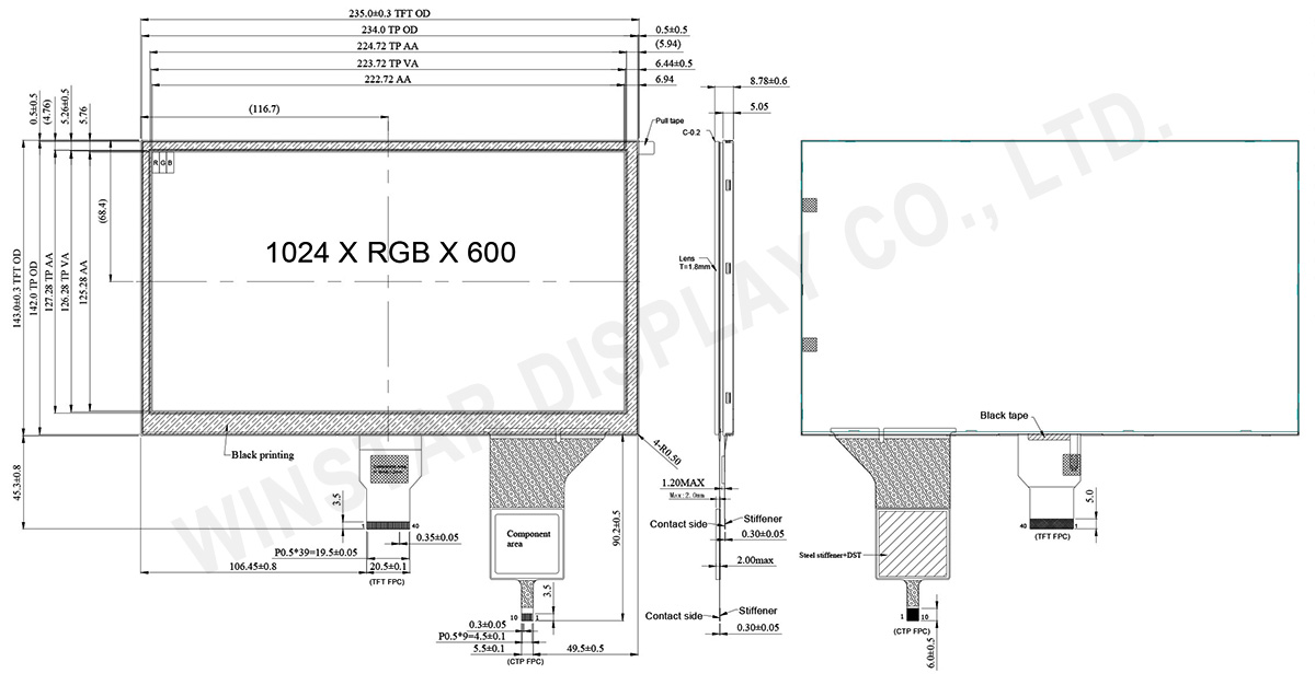
| Module dimension |
235(W) x 143(H) x 8.78(D) |
mm |
| Active area |
222.72 (H) x 125.28(V) |
mm |
| Pixel pitch |
0.2175(W) x 0.2088(H) |
mm |
| LCD type |
TFT, Normally Black, Transmissive |
| Interface |
LVDS |
| Driver IC |
EK79001HN + EK73215BCGA or equivalent |
| Viewing Angle |
85/85/85/85 |
| Aspect Ratio |
16:9 |
| Backlight Type |
LED, Normally White |
| PCAP IC |
ILI2511 or equivalent |
| PCAP Interface |
USB (I2C available) |
| PCAP FW Version: |
V6.0.0.0.62.90.1.2 |
| Touch Panel |
With PCAP |
| Surface |
Glare |
Absolute Maximum Ratings
| Item |
Symbol |
Min |
Typ |
Max |
Unit |
| Operating Temperature |
TOP |
-20 |
- |
+70 |
℃ |
| Storage Temperature |
TST |
-30 |
- |
+80 |
℃ |
Electrical Characteristics
Typical Operation Conditions (At Ta = 25 °C,)
| Item |
Symbol |
Min |
Typ |
Max |
Unit |
| Digital Power Supply Voltage For LCD |
VDD |
3 |
3.3 |
3.6 |
V |
| Analog Power Supply Voltage |
AVDD |
9.89 |
10.2 |
10.5 |
V |
| Gate On Power Supply Voltage |
VGH |
19.4 |
20.0 |
20.6 |
V |
| Gate Off Power Supply Voltage |
VGL |
-10.3 |
-10.0 |
-9.7 |
V |
| Common Power Supply Voltage |
VCOM |
4.0 |
4.3 |
4.6 |
V |
| Input logic high voltage |
VIH |
0.7 VDD |
- |
VDD |
V |
| Input logic low voltage |
VIL |
0 |
- |
0.3 VDD |
V |
| Supply PCAP |
USB_VDD 5V |
4.4 |
5.0 |
5.5 |
V |
| I VDD 5V |
— |
97.8 |
120 |
mA |
Interface
TFT LCD Module
| Pin No. |
Symbol |
Description |
| 1 |
VCOM |
Common voltage |
| 2 |
VDD |
Digital power |
| 3 |
VDD |
Digital power |
| 4 |
NC |
Not connect |
| 5 |
Reset |
Global reset pin. Active low to enter reset state. Suggest to connecting with an RC reset circuit for stability. Normally pull high. (R=10KΩ,C=1μF) |
| 6 |
STBYB |
Standby mode, normally pull high STBYB=”1”, normal operation STBYB=”0”,timing control, source driver will turn off, all output are high-Z |
| 7 |
GND |
Digital ground |
| 8 |
RXIN0- |
Negative LVDS differential data inputs |
| 9 |
RXIN0+ |
Positive LVDS differential data inputs |
| 10 |
GND |
Digital ground |
| 11 |
RXIN1- |
Negative LVDS differential data inputs |
| 12 |
RXIN1+ |
Positive LVDS differential data inputs |
| 13 |
GND |
Digital ground |
| 14 |
RXIN2- |
Negative LVDS differential data inputs |
| 15 |
RXIN2+ |
Positive LVDS differential data inputs |
| 16 |
GND |
Digital ground |
| 17 |
RXCLKN- |
Negative LVDS differential clock inputs |
| 18 |
RXCLKN+ |
Positive LVDS differential clock inputs |
| 19 |
GND |
Digital ground |
| 20 |
RXIN3- |
Negative LVDS differential data inputs |
| 21 |
RXIN3+ |
Positive LVDS differential data inputs |
| 22 |
GND |
Digital ground |
| 23 |
NC |
Not connect |
| 24 |
NC |
Not connect |
| 25 |
GND |
Digital ground |
| 26 |
NC |
Not connect |
| 27 |
NC |
Not connect |
| 28 |
SELB |
6-bit/8-bit input select SELB = L , 8-bit ; SELB = H , 6-bit |
| 29 |
AVDD |
Analog power |
| 30 |
GND |
Digital ground |
| 31 |
LED- |
LED Cathode |
| 32 |
LED- |
LED Cathode |
| 33 |
L/R |
Left or right display control |
| 34 |
U/D |
Up / down display control |
| 35 |
VGL |
Negative power for TFT |
| 36 |
NC |
Not connect |
| 37 |
NC |
Not connect |
| 38 |
VGH |
Positive power for TFT |
| 39 |
LED+ |
LED Anode |
| 40 |
LED+ |
LED Anode |
When L/R=”0”,set right to left scan direction.
When L/R=”1”,set left to right scan direction.
When U/D=”0”,set top to bottom scan direction.
When U/D=”1”,set bottom to top scan direction.
PCAP PIN Definition
| Pin |
Symbol |
Function |
| 1 |
USB_VSS |
System ground |
| 2 |
USB_VDD 5V |
Power supply |
| 3 |
USB_D+ |
Data + |
| 4 |
USB_D- |
Data - |
| 5 |
VSS |
System ground |
| 6 |
SDA |
I2C data input and output |
| 7 |
SCL |
I2C clock input |
| 8 |
RST |
External Reset, Low is active |
| 9 |
INT |
External interrupt to the host |
| 10 |
VDDT 3.3 |
Power supply |
ips 10.1, 10.1 inch ips display, 10.1 ips, 10.1 ips display