Home Products Smart Display RS485 Smart Display WL0F0007000A8GDADSA02

7-inch RS485 Modbus Smart Display with PCAP Touch and 32MB Flash

Model No. WL0F0007000A8GDADSA02

►TFT Size: 7"
►TFT Resolution: 1024×600 dots
►TFT View Direction: 85/85/85/85 (IPS)
►TFT Touch Screen: Projected capacitive touch screen (PCAP)
►Communication Interface: RS485
►Protocol: Modbus + GPIO
►Brightness(cd/m²): 450

Description

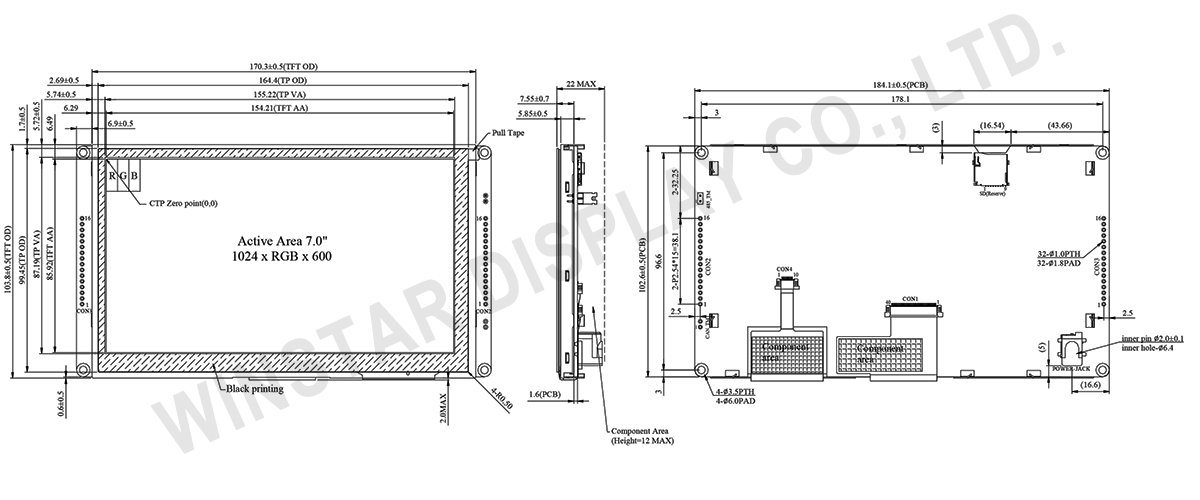
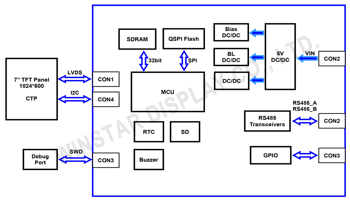
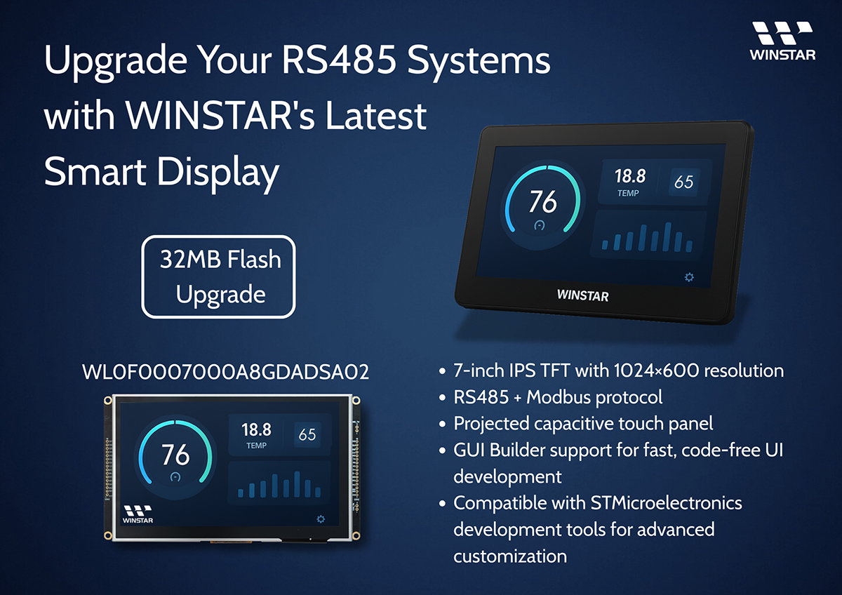
WL0F0007000A8GDADSA02 is a 7-inch RS485 series smart display designed as a slave device that displays screens and reports touch status based on commands from a master device. This module consists of an IPS TFT display WF70A8TYAHLNGB paired with built-in firmware on a 4-layer FR4 PCB, integrating touch, display, and control functions.

This product is easy to use, significantly reducing development time and cost, accelerating project time-to-market. It supports multiple host platforms, including PCs (via USB to RS-485), MCUs, SBCs, and Raspberry Pi.

Features of the 7-inch RS485 smart display:

  • +12V power supply input (range: 8V–35V) with dynamic range support, power consumption approximately 6W.
  • Power-on self-test with automatic screen activation after booting.
  • RS485 communication interface supporting Modbus protocol.
  • Built-in or external 32MB flash memory for storing fonts, graphical objects, and Object Dictionary Data.
  • Supports projected capacitive touch panel (PCAP) and buzzer control (controlled by master device).
  • Compatible with multiple platforms such as PC (with USB to RS485 dongle), MCU, and Raspberry Pi.
  • GPIO pins support 3.3V TTL signals with a maximum tolerance of 5.5V.
  • Includes GUI Builder for interface design without programming. User guide
  • Equipped with STM32F series MCU and supports ST development tools.
  • Extended memory management, including:
    • Up to 255 objects per page (vs. 64 in the 16MB version).
    • Up to 1000 total objects (vs. 500 in the 16MB version).
    • Support for up to 64 pages (vs. 30 in the 16MB version).
    • Dynamic memory allocation for efficient flash storage management.
 

Upgrade Your RS485 Systems with WINSTAR's Latest  Smart Display (32MB Flash Upgrade)  - WL0F0007000A8GDADSA02


Winstar provides a Windows-based GUI Builder that allows drag-and-drop design and real-time preview, enabling fast WYSIWYG interface creation. The latest version integrates three application templates (Industrial / Automotive / Medical). Users can switch templates by pressing the option key for 3 seconds at startup, or change templates anytime via the GUI Builder.

Try before you buy! Contact us to download WINSTAR GUI Builder application.

Smart Display products are designed with STMicroelectronics' (ST) controller which supports ST development tools like TouchGFX and STM32CubeIDE. You can also use ST tools to design WINSTAR Smart Display modules besides GUI builder.

  • TouchGFX: An advanced free-of-charge graphic software framework optimized for STM32 microcontrollers.
  • STM32CubeIDE: An advanced C/C++ development platform with peripheral configuration, code generation, code compilation, and debug features for STM32 microcontrollers and microprocessors.
  • STM32CubeMX: A graphical tool that allows a very easy configuration of STM32 microcontrollers, as well as the generation of the corresponding initialization C code for the Arm® Cortex®-M core or a partial Linux® Device Tree for Arm® Cortex®-A core, through a step-by-step process.
  • STM32CubeProg: An all-in-one multi-OS software tool for programming STM32 products. It provides an easy-to-use and efficient environment for reading, writing and verifying device memory through both the debug interface (JTAG and SWD) and the bootloader interface (UART, USB DFU, I2C, SPI, and CAN).
 

If you have purchased a WINSTAR Smart Display and wish to develop it by TouchGFX, please contact us through our website to obtain the initial code.

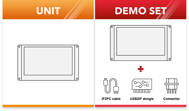
We also provide demo set with all needed accessories for you to realize your GUI design on smart displays.
We also provide demo set with all needed accessories for you to realize your GUI design on displays.


DRAWING

7-inch RS485 Modbus Smart Display with PCAP Touch and 32MB Flash - WL0F0007000A8GDADSA02

Block Diagram

WL0F0007000A8GDADSA02 - Block Diagram

SPECIFICATIONS

General Specifications

Item Standard Value Unit
Operating voltage 8~35V Vdc
Communication Interface RS485 -
MCU STM32F746 N/A
Flash Memory 32 MB
SDRAM Memory 16 MB
LCD display size 7.0 inch
Pixel pitch 1024 x RGB x 600(TFT) dots
Module dimension 184.1(W) x 103.8(H) x 22(D) mm
Active area(AA) 154.2144 x 85.92 mm
Pixel pitch 0.1506 x 0.1432 mm
Brightness Min:400; Typ:450 cd/m2
LCD type TFT, Normally Black, Transmissive
Viewing Angle 85/85/85/85
Aspect Ratio 16:9
Touch Panel Projected Capacitive Touch Panel (PCAP)
Surface Glare

Absolute Maximum Ratings

Item Symbol Min Typ Max Unit
Operating Temperature TOP -20 +70
Storage Temperature TST -30 +80

Electrical Characteristics

Item Symbol Condition Min Typ Max Unit
Supply Voltage VIN 8 12 35 V
Supply current I(mA) - 520 - mA

BOM

Item Description
LCM WF70A8TYAHLNGB#
PCBA SV10007R00A8K00N0108

Interface Pin Function

CON2 definition

Pin Symbol Function Remark
1 Reserve _ _
2 Reserve _ _
3 Reserve _ _
4 Reserve _ _
5   Reserve _ _
6 Reserve _ _
7 Reserve _ _
8 Reserve _ _
9 NC _ _
10 Reserve _ _
11 Reserve _ _
12 Reserve _  
13 VIN Power supply V+ input _
14 RS485_B RS485 B  I/O
15 RS485_A RS485 A  I/O
16 GND Power supply GND input _


CON3 definition

Pin Symbol Function Remark
1 +3V3 3.3V power for JTAG interface Output
2 SWCLK CLK pin for JTAG interface Input
3 GND GND for JTAG interface Output
4 SWDIO Data pin for JTAG interface I/O
5 NRST Reset pin for JTAG interface Input
6 GND Power GND Output
7 Wkup WKup,ADC,Timer,Event,I/O Input
8 BOOT0 Lo: Internal flash boot (Default)
Hi: External flash boot
Input
9 IO_0 ADC,DAC,Timer,Event,I/O @3.3V PA5
10 IO_1 ADC,Timer,Event,I/O @3.3V PA6
11 IO_2 ADC,Timer,Event,I/O @3.3V PA7
12 IO_3 ADC,Timer,Event,I/O @3.3V PA8
13 IO_4 ADC,Timer,Event,I/O @3.3V PC13
14 IO_5 ADC,Timer,Event,I/O @3.3V PB11
15 IO_6 ADC,Timer,Event,I/O @3.3V PA15
16 IO_7 RST,ADC,Event,I/O @3.3V PD11

@3.3V : I/O allow below 3.3V input, If exceeding 3.3V may cause MCU damag

Recently Viewed

go top
close

We value your privacy

By clicking "Allow All Cookies", you agree to the storing of cookies on your device to enhance site navigation, analyse site usage, and assist in our marketing and performance efforts. You can find further information this subject in our policy.

We value your privacy

Winstar and certain third parties use cookies on www.winstar.com.tw. The details regarding the types of
cookies, their purpose and the third parties involved are described below and in our Cookie Policy.
Please click on “Allow All” to consent to our usage of cookies in order to have the best possible
experience on our websites. You can also set your preferences or reject cookies (except for strictly
necessary cookies).

Manage Consent Preferences

Always Active
Essential Cookies

These cookies are essential in order to enable you to move around the website and use its
features, such as setting your privacy preferences, logging in or filling in forms.

Analytics Cookies

Also known as “statistics cookies,” these cookies collect information about how you use a website, like which pages you visited and which links you clicked on. See Detail