How Does a Host Control Smart Display via CANopen? (Gauge Control Example)
May 04,2022
Introduction
In previous introductions to Smart Display, we focused primarily on its functions and features rather than how it can be controlled by a host in the customer's end application. This article uses a gauge as an example to demonstrate how data from a physical control and the host (Arduino) can be transmitted to the Smart Display module to update the display.
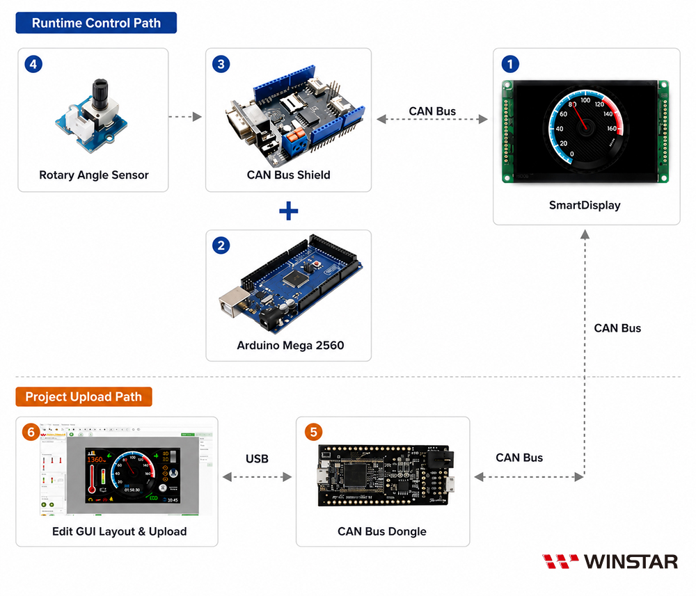
This example uses a 4.3-inch Smart Display with CAN Bus to display a 240-degree gauge controlled by a host. The host consists of an Arduino Mega 2560, a CAN Bus Shield, and a Rotary Angle Sensor. The required components are listed below:
4.3-inch Smart Display with CAN Bus
Arduino Mega 2560
CAN Bus Shield
Rotary Angle Sensor
CAN Bus Dongle
GUI Builder
System Diagram
Step 1: Design the Project in GUI Builder
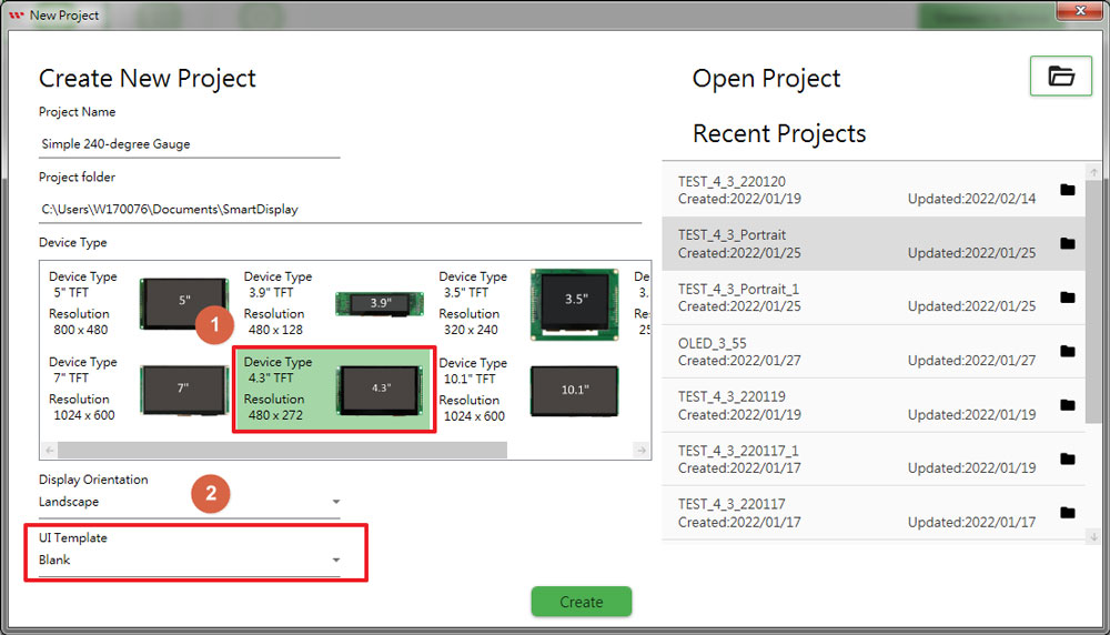
1.1 Create a new project and select the 4.3" Display blank template in GUI Builder.
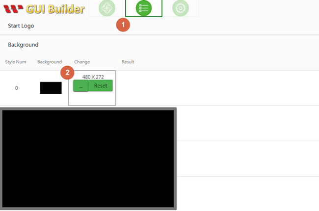
1.2 Change Background Style 0 in the Resource panel by selecting the black screen image file.
1.3 Edit the rotation angle of the needle in the Gauge Edit window.
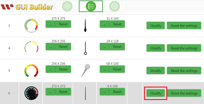
►First, click the Modify button for Gauge Style 6.
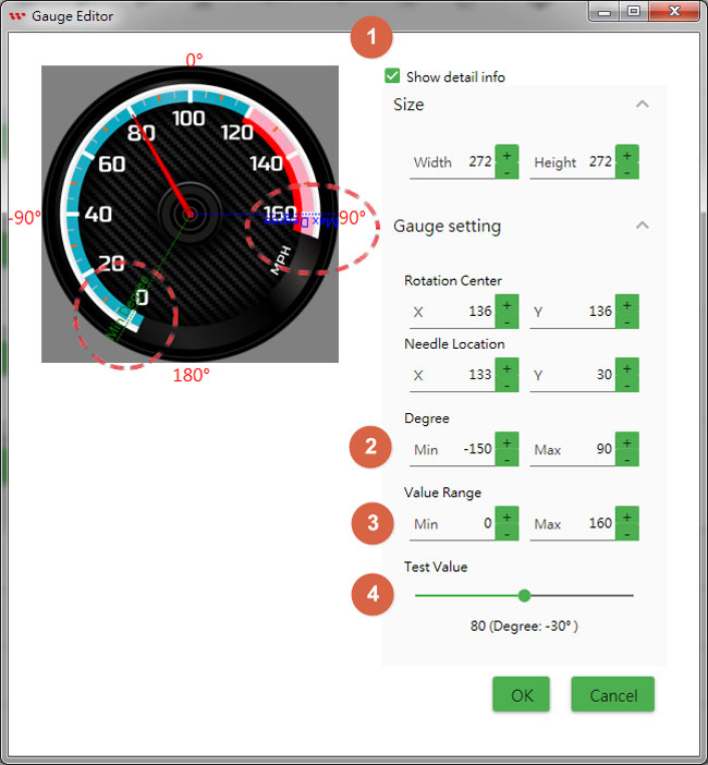
►Once selected, a preview of the gauge will appear in the Gauge Editor window, as shown below.
►Select the "Show Details" checkbox to view more information about the needle rotation.
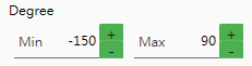
►The minimum and maximum angles of the needle can be adjusted using the +/- buttons in the Degree area, as shown below.
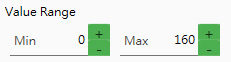
►The Value Range is defined by minimum and maximum values, which are mapped to the needle's minimum and maximum rotation angles when a value is received via CAN Bus.
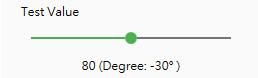
►After completing the gauge design, you can check the result by dragging the Test Value track bar to the right. The needle angle will increase until the maximum value/degree is reached.
Step 2: Build and Upload the Project
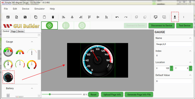
2.1 After completing the previous steps, switch to the Page Info sheet and drag Gauge Style 6 to the center of the screen.
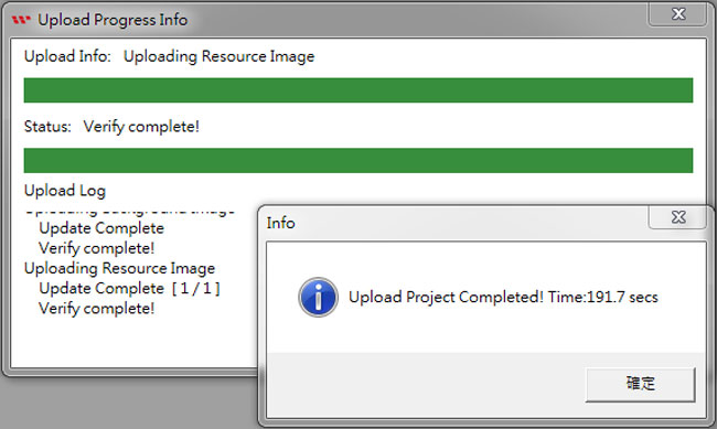
2.2 Connect the PC to the Smart Display via USB2CAN, then click the "Connect Device" and "Upload the Project" icons. The resource and page settings will be uploaded to the Smart Display module via GUI Builder, as shown below:
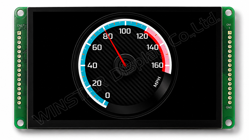
2.3 The screen switches from the startup screen to the operation screen. When the following screen appears on the 4.3-inch Smart Display with CAN Bus, the upload has been completed successfully.
Step 3: Program the Arduino Host
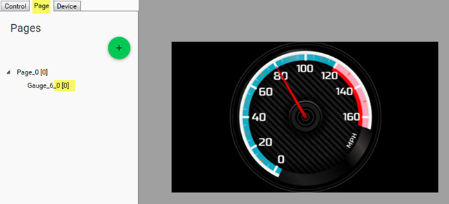
3.1 Switch to the Page sheet in GUI Builder. The index of Gauge Style 6 corresponds to object 0 (0x2000) as defined in the CANopen structure. It is important to note the object's index. If the index is known, the object's status can be polled or changed by the Arduino host, as shown in the sample code below.
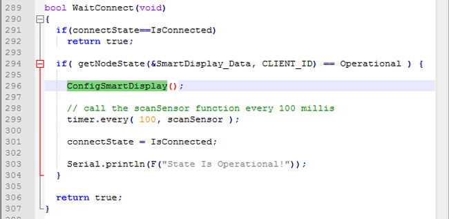
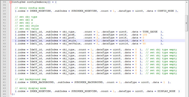
3.2 The Arduino host can use the "ConfigSmartDisplay" function to set the type, x/y position, style, configuration, and background image of object 0. Alternatively, the Smart Display can read the existing object data from the onboard flash (uploaded by GUI Builder) and display the configured objects on the screen without additional programming by the Arduino host.
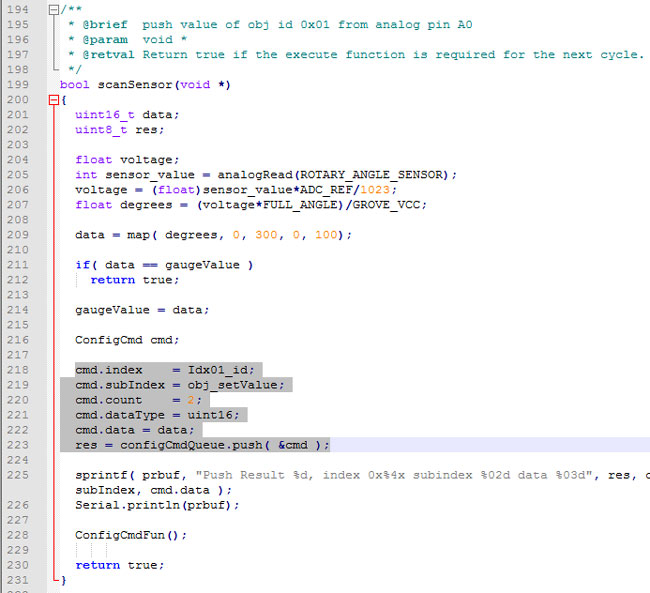
3.3 When the Arduino host receives a value change from the physical Rotary Angle Sensor, it sends the corresponding value to the Smart Display via CANopen.
Please refer to the following program for the key command structure IDs and sub-indexes. The purpose of this program is to update the gauge value (object index 0) according to the value received from the physical Rotary Angle Sensor.
By clicking "Allow All Cookies", you agree to the storing of cookies on your device to enhance site navigation, analyse site usage, and assist in our marketing and performance efforts. You can find further information this subject in our policy.