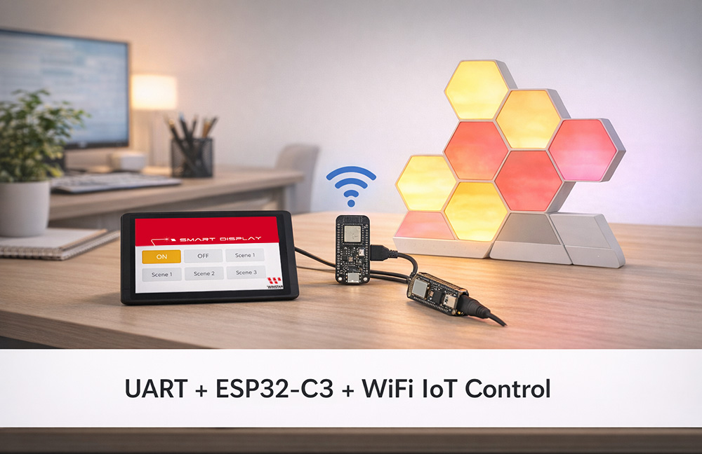
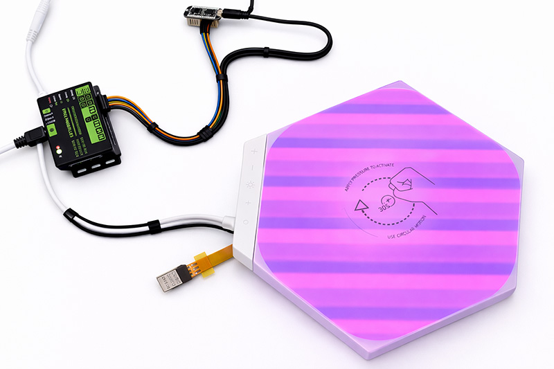
The Smart Display serves as a human-machine interface, communicating with the ESP32-C3 module via UART serial communication. The ESP32-C3 is responsible for WiFi connectivity and calling the Open API of the Nanoleaf Shapes smart light panels to achieve light control and scene query testing. This document focuses on the Smart Display sending custom UART commands to the ESP32-C3 for preliminary testing, verifying the feasibility of UART communication, WiFi networking, and Nanoleaf API calls. This phase lays the foundation for a subsequent complete smart display control system, proving the reliability of UART bridging and IoT API integration.
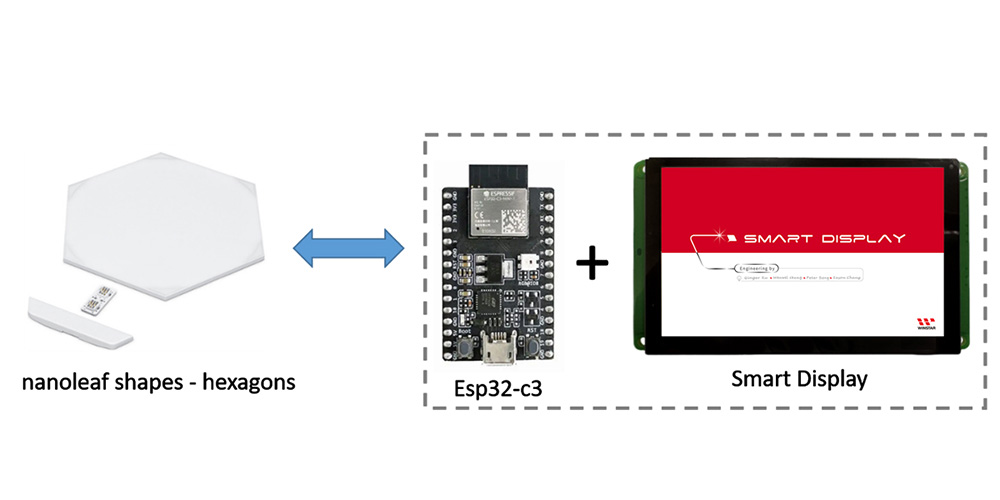
System Architecture
Smart Display ↔ UART ↔ ESP32-C3 ↔ WiFi ↔ Nanoleaf Shapes (Open API)
Hardware Requirements
1.Smart Display
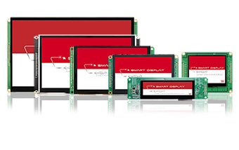
- WINSTAR Smart Display (supports TouchGFX GUI)

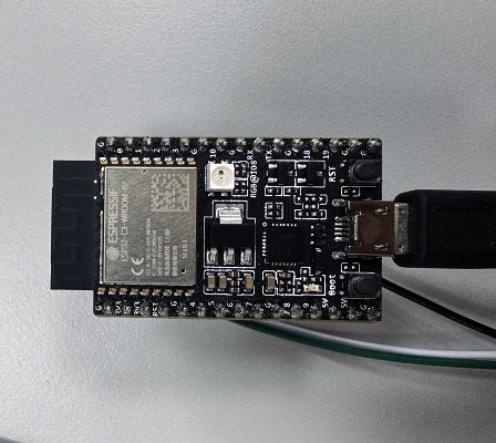
2.ESP32-C3-DevKitC-02
- Power converter: Input 5V, output 3.3V.
3.Nanoleaf Shapes
- Communication protocol: WiFi (2.4 GHz b/g/n)
- Voltage: 100VAC - 240VAC
- Maximum power: 42W
- Maximum power consumption per panel: 2W
PC Control Testing
1.Setting Up Nanoleaf Shapes
⏹︎ Pairing Shapes Device via Mobile App (iOS)
- You can find the official Nanoleaf App in the App Store.
- Pair Your Shapes
- On the Dashboard, tap the pencil icon in the top right corner.
- Tap “Add Device +”
- The app will automatically open up the pairing window.
- Follow the instructions on the screen to either:
Option A: Scan the QR code
Option B: Enter in the 8-digit pairing code found on your Power Supply Unit, Controller, or Quick Start Guide/Welcome Card
Option C: Use NFC Tap, by holding the top of your mobile device over the buttons of your Controller
- Your Nanoleaf Shapes should now be connected and ready to go
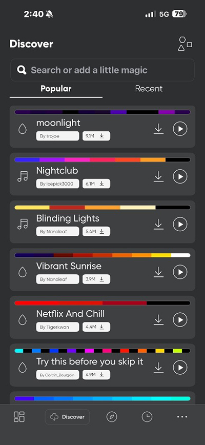
⏹︎ Downloading Scenes to Nanoleaf Shapes
2.Setting Up ESP32-C3
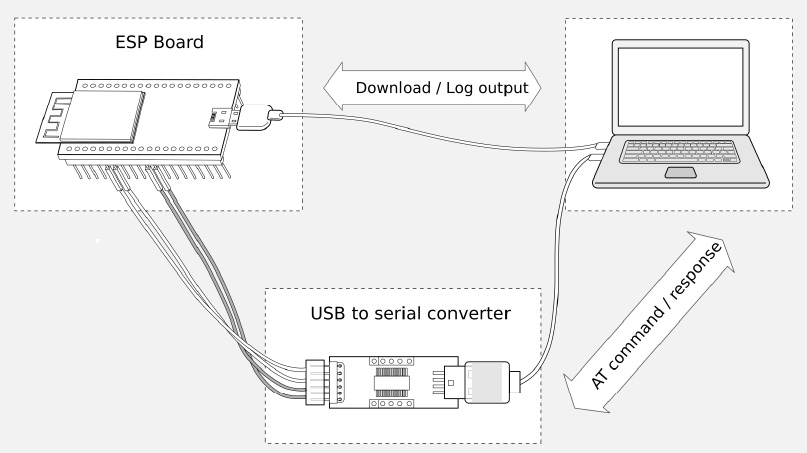
⏹︎ Configuring ESP32-C3 via PC
PC-->USB to UART converter-->esp32-c3
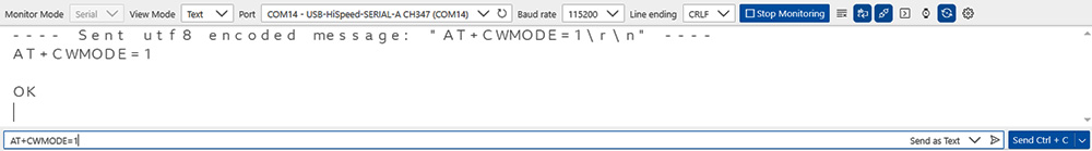
⏹︎ Setting Station Mode
The WiFi modes of ESP32-C3 are similar to those of ESP32 and ESP8266, supporting the following three common modes:
- Station mode (STA mode): ESP32-C3 acts as a client, connecting to an existing WiFi router (e.g., home network). In this mode, the device can access the internet or communicate with other devices on the network but does not create its own hotspot. Application example: Sensors uploading data to the cloud (e.g., MQTT, HTTP).
- SoftAP mode (AP mode, Soft Access Point): ESP32-C3 itself becomes a WiFi hotspot, allowing other devices (e.g., phones, computers) to connect directly to it. Typically used for initial network configuration or local control. Default SSID is usually something like "ESP32-AP", with default IP 192.168.4.1. ESP32-C3 supports up to 4 simultaneous client connections (slightly fewer than ESP8266). Application example: Using a mobile app (e.g., EspTouch, web configuration page) to input home WiFi credentials.
- Station + SoftAP mode (STA+AP concurrent mode): Both STA and AP modes are enabled simultaneously. ESP32-C3 connects to the router for internet access while providing its own hotspot for direct phone connection. This is the most common mode for smart home applications: Normal cloud reporting while allowing local control by phone even without internet. Note: ESP32-C3 has a single antenna, so both modes share the same channel, resulting in slightly lower performance than single mode, but sufficient for most applications.
AT: AT+CWMODE=1
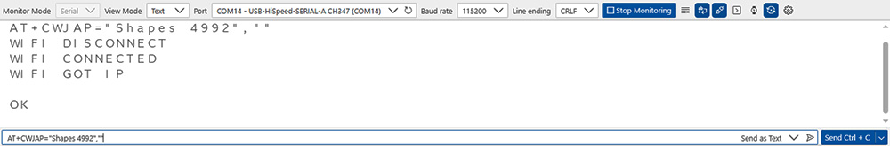
⏹︎ Connecting to Nanoleaf Shapes Hotspot (No Password in Pairing Mode)
- AT+CWJAP: ESP32-C3 (in Station mode) connects to the specified WiFi access point.
- "Shapes 4992": This is the WiFi SSID of the Nanoleaf Shapes light panel.
- "": Empty password (Nanoleaf panels in initial setup or reset pairing mode typically have an open, passwordless hotspot).
AT: AT+CWJAP="Shapes 4992",""
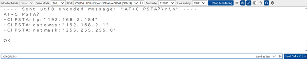
⏹︎ Querying Obtained IP
ESP32-C3 will obtain an IP assigned by the panel (usually in the 192.168.x.x segment).
AT: AT+CIPSTA?
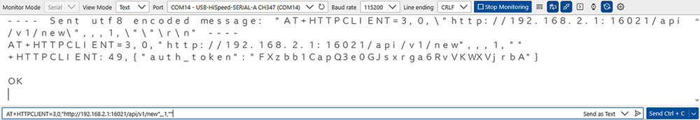
⏹︎ Obtaining Nanoleaf Token (Long-press Controller to Enter Pairing Mode)
- The address is fixed at http://192.168.2.1:16021/api/v1/new on the panel's hotspot.
- Success returns JSON like {"auth_token": "your long token"}. First, put the Shapes into pairing mode.
First, put the Shapes into pairing mode.

Obtain Shapes token:
AT:AT+HTTPCLIENT=3,0,"http://192.168.2.1:16021/api/v1/new",,,1,""
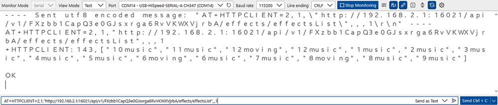
⏹︎ Retrieve the Nanoleaf Shapes Scene List
AT+HTTPCLIENT is a commonly used HTTP client command, suitable for interacting with the Nanoleaf API (e.g., retrieving information, querying scene lists, etc.)
AT:AT+HTTPCLIENT=2,1,"http://192.168.2.1:16021/api/v1/FXzbb1CapQ3e0GJsxrga6RvVKWXVjrbA/effects/effectsList",,,1
⏹︎ Controlling Shapes to Turn On Lights
Use HTTP PUT to send a request to turn on the lights.
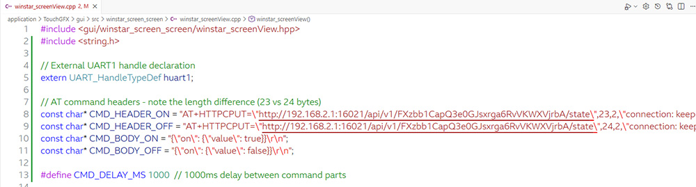
AT:AT+HTTPCPUT="http://192.168.2.1:16021/api/v1/FXzbb1CapQ3e0GJsxrga6RvVKWXVjrbA/state",23,2,"connection: keep-alive","content-type: application/json"
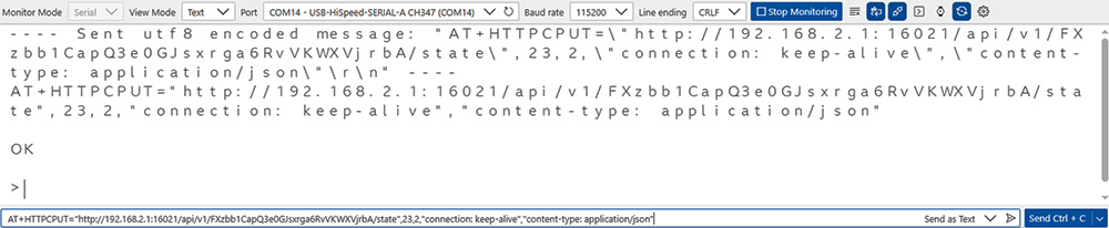
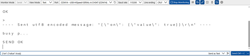
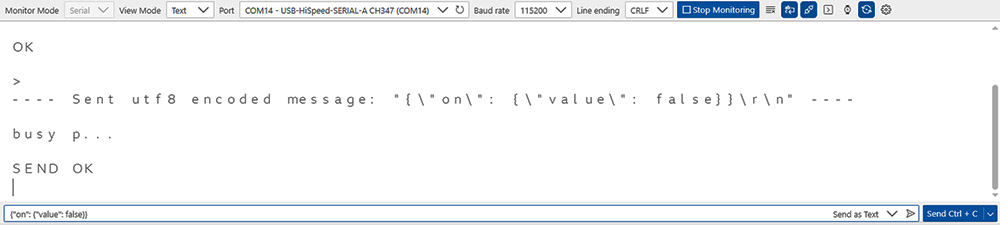
AT: {"on": {"value": true}}
⏹︎ Controlling Shapes to Turn Off Lights
Use HTTP PUT to send a request to turn off the lights.
AT:AT+HTTPCPUT="http://192.168.2.1:16021/api/v1/FXzbb1CapQ3e0GJsxrga6RvVKWXVjrbA/state",24,2,"connection: keep-alive","content-type: application/json"
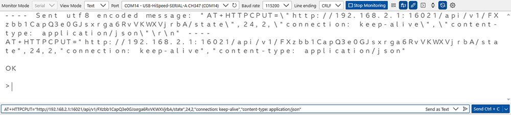
AT: {"on": {"value": false}}
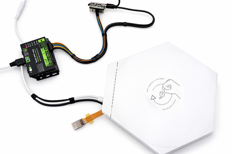
Integration Testing (Smart Display + ESP32-C3)
Development Environment:
- STM32CubeIDE: 1.16.0
- TouchGFX : 4.24.2 Designer
1.TouchGFX Design (Creating a Button)
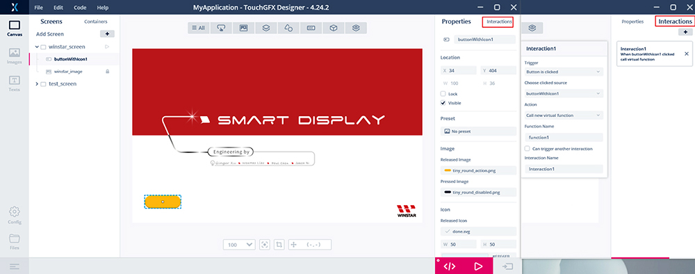
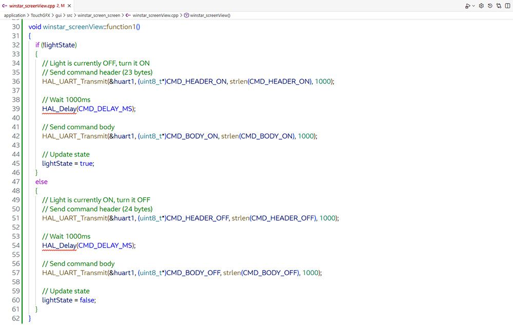
2.Program Implementation (winstar_screenView.cpp)
Add a UART transmission function with a custom simple command protocol.
Button click event: Toggle state and send corresponding UART command.
3.Testing Turn On and Turn Off Lights
Click Button1: First click turns on lights, second click turns off lights.
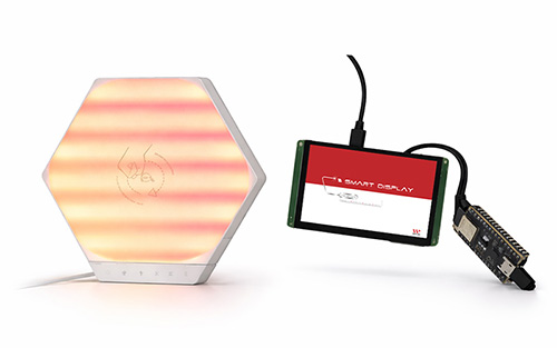 Click Button1 to turn on lights
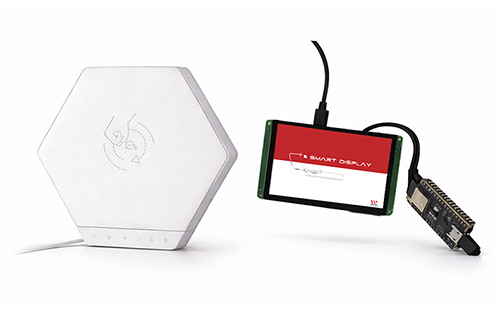 Click Button1 again to turn off lights
Conclusion
This test successfully verifies that the Smart Display can effectively control the ESP32-C3 module via UART serial commands to connect to the network and call the Nanoleaf Shapes API, quickly implementing the on/off function for the Nanoleaf Shapes light panels. This lays the foundation for subsequent development of a touch-based graphical user interface (GUI) for light control. The system has low latency, high stability, and reliable communication. In the future, it can be expanded to full light control (e.g., brightness adjustment, color changes, dynamic scene switching), and display panel status, real-time feedback, or custom control panels on the Smart Display, further integrating more IoT applications.
References