Home Products E-paper Display WAA0420A2ADB5NXXX000

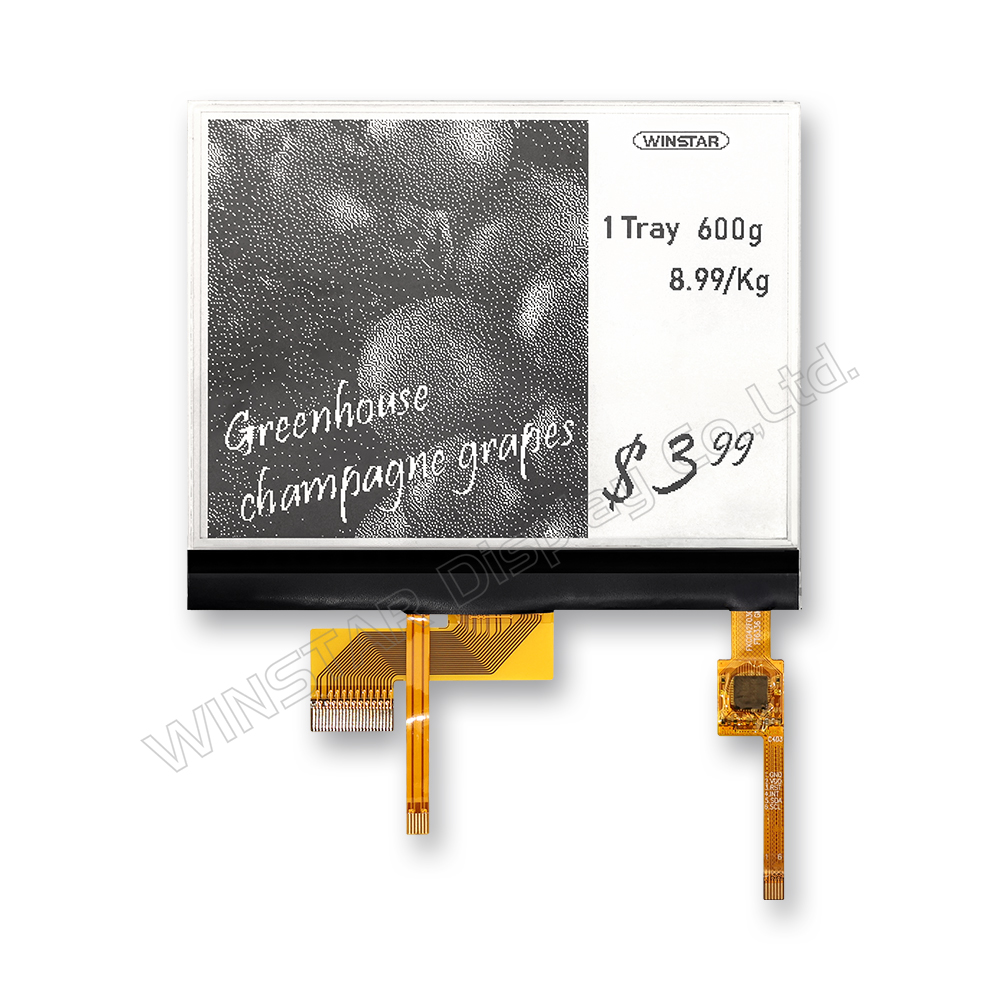
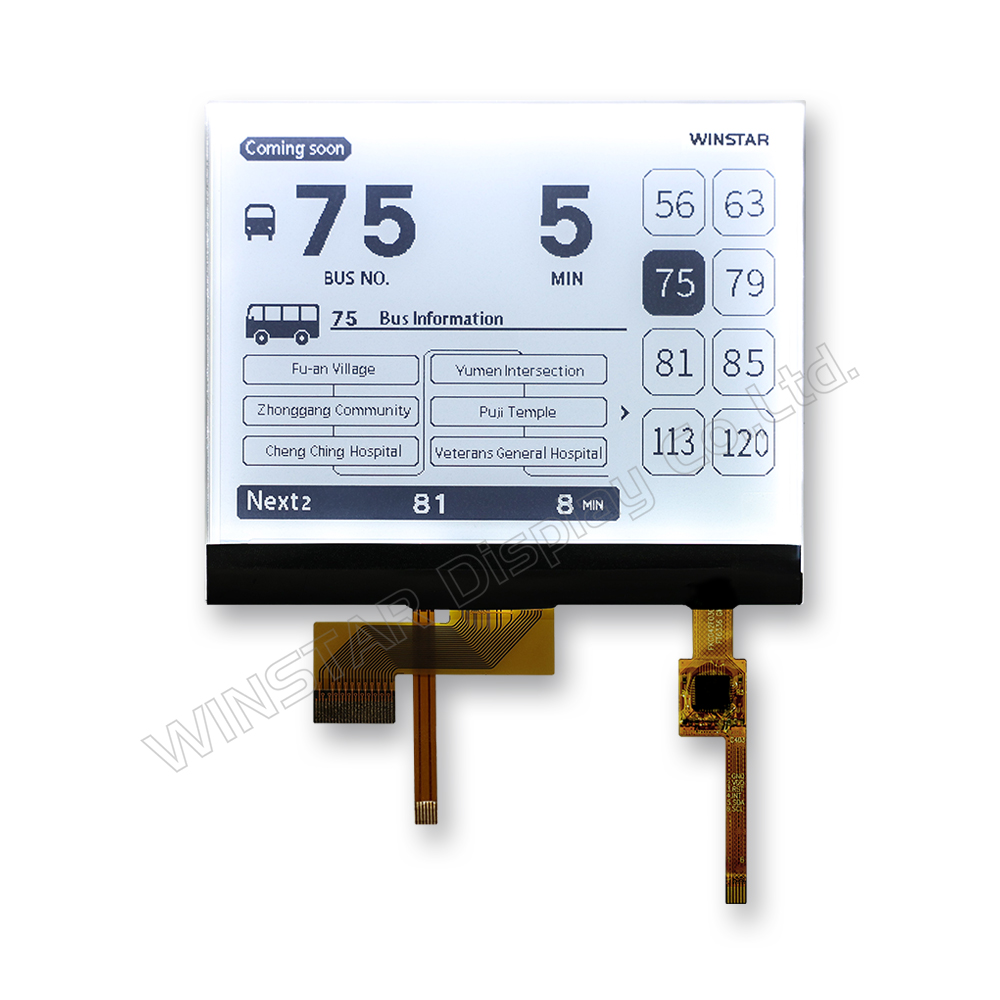
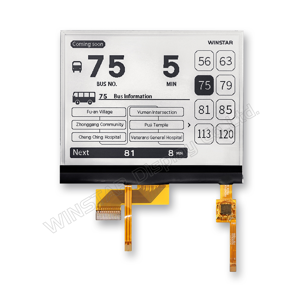
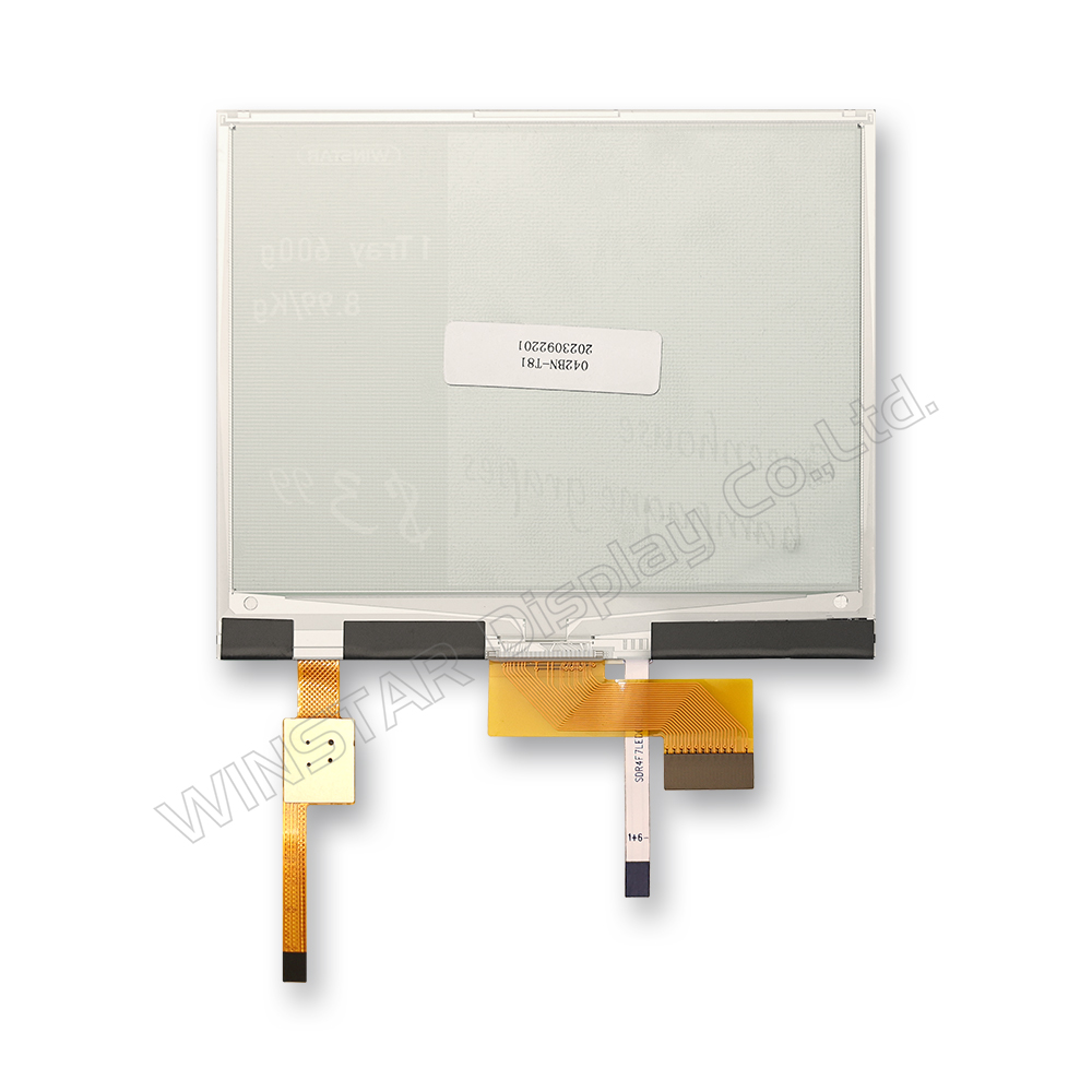
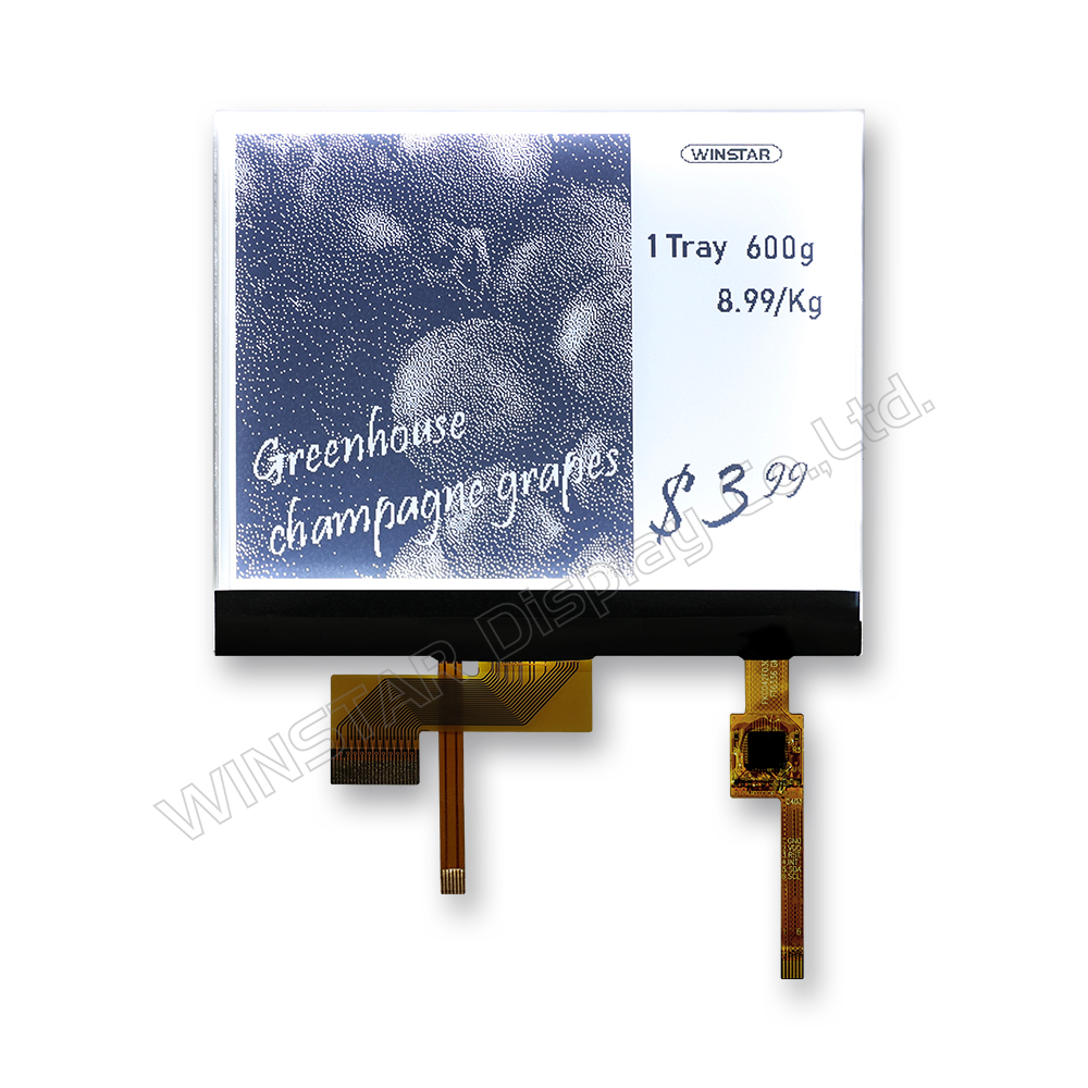
4.2-inch Electronic Paper Display with Front Light and Capacitive Touch

Model No. WAA0420A2ADB5NXXX000

►Size: 4.2 inch E-paper display module
►Resolution: 400x300 dots
►Interface: MCU / SPI
►Touch Screen : With capacitive touch panel
►The display refreshes black-and-white e-paper displays.
►Front Light : Yes

Description

The WAA0420A2ADB5NXXX000 is a 4.2-inch Electronic Paper Display (EPD) module featuring a front light panel and capacitive touch functionality. This display supports 1-bit black-and-white image rendering with a resolution of 400×300 pixels. It is built on a TFT backplane that drives the electrophoretic layer, and integrates a variety of functional circuits including gate driver, source driver, MCU interface, timing controller, oscillator, DC-DC converter, SRAM, LUT, and VCOM generator.

This module is designed for ultra-low power consumption and high-visibility environments, making it ideal for a range of paperless applications in both commercial and industrial settings.

Key Features

  • 400×300 pixel resolution
  • High contrast and reflectance
  • Ultra-wide viewing angle
  • Extremely low power consumption
  • Pure reflective display technology
  • Bi-stable image retention
  • Operable in commercial temperature range
  • Supports both portrait and landscape orientations
  • Hard-coated, anti-glare display surface
  • Integrated display RAM
  • Waveform storage in on-chip OTP or programmable via MCU
  • Serial Peripheral Interface (SPI) available
  • On-chip oscillator
  • Integrated booster and regulator for VCOM, Gate, and Source voltages
  • I²C master interface for external temperature sensor reading
  • Partial screen update supported
  • Built-in temperature sensor

Applications

The 4.2-inch Electronic Paper Display is not only suitable for Electronic Shelf Label (ESL) systems, but also well-suited for a broad range of low-power, high-clarity display solutions including:

  • Industrial equipment labels – real-time machine status or maintenance info
  • Smart meeting room nameplates – dynamic display of meeting schedules and names
  • Warehouse & logistics tags – barcode and inventory information updates
  • Medical & healthcare labels – bedside patient information or device displays
  • Retail POP signage – promotional messages, pricing, or QR codes
  • Smart home control panels – status indicators for lighting, HVAC, or security
  • Library and museum digital labels – exhibit details or shelf identification

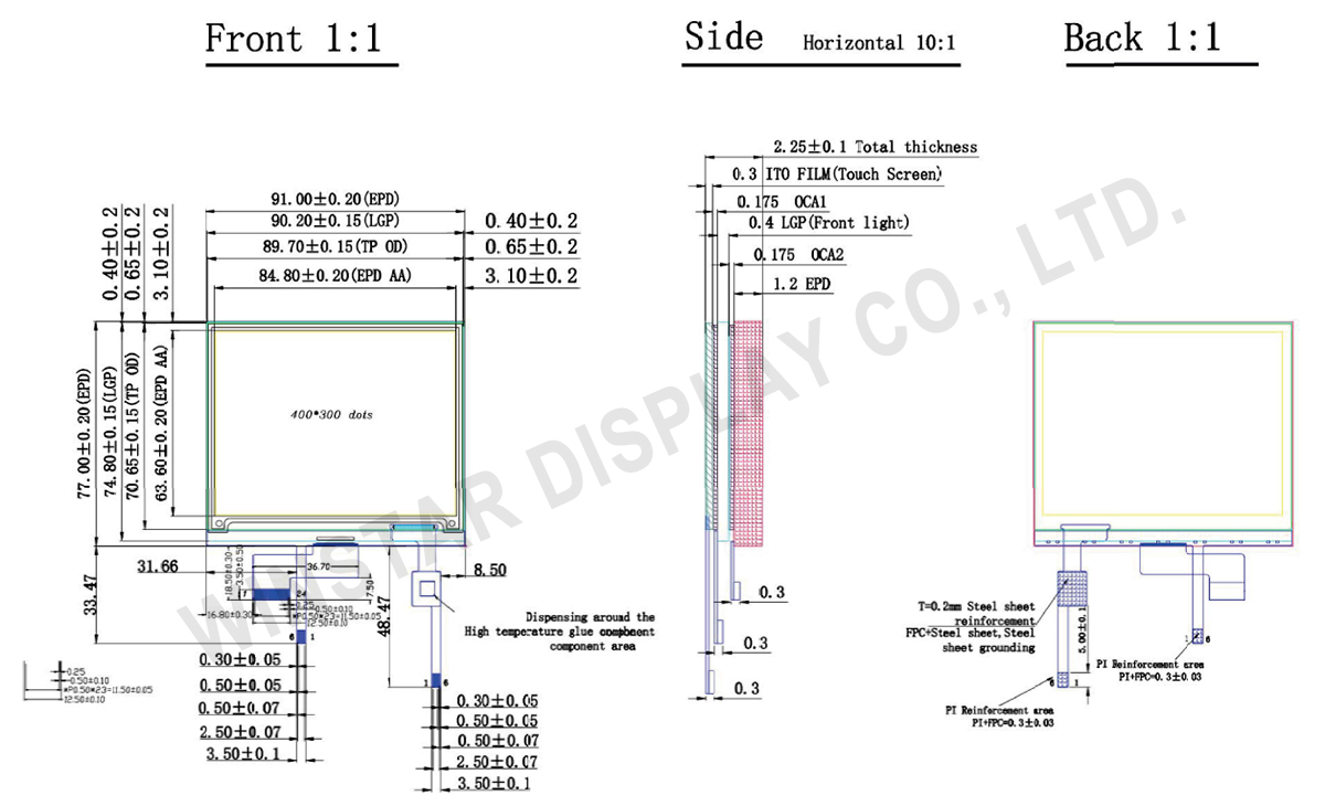
DRAWING

WAA0420A2ADB5NXXX000

SPECIFICATIONS

General Specifications

Parameter Specifications Unit
Screen Size 4.2 Inch
Display Resolution 400(H)×300(V) Pixel
Active Area 84.8(H)×63.6(V) mm
Pixel Pitch 0.212×0.212 mm
Pixel Configuration Rectangle  
Outline Dimension 91(H) × 77 (V) × 2.02(D) mm
Module Weight 16.1±0.3 g

Electrical Characteristics

Absolute Maximum Ratings

Parameter Symbol Rating Unit
Logic supply voltage VCI -0.5 to +6.0 V
Logic Input voltage VIN -0.5 to VCI +0.5 V
Logic Output voltage VOUT -0.5 to VCI +0.5 V
Operating Temp range TOPR 0 to +50 ºC
Storage Temp range TSTG -25 to+70 ºC
Optimal Storage Temp TSTGo 23±2 ºC
Optimal Storage Humidity HSTGo 55±10 %RH

Input /Output Pin Assignment

No. Name I/O Description
1 NC   Do not connect with other NC pins
2 GDR O N-Channel MOSFET Gate Drive Control
3 RESE I Current sense input for control loop.
4 NC NC Do not connect with other NC pins
5 VSH2 C Positive source driving voltage (Red)
6 TSCL O I2C interface to digital temperature sensor Clock pin
7 TSDA I/O I2C interface to digital temperature sensor Data pin
8 BS1 I Bus Inteface selection pin
9 BUSY O Busy state output pin
10 RES# I Reset signal input. Active Low
11 D/C# I Data / Command control pin
12 CS# I Chip select input pin
13 SCL I Serial Clock pin (SPI)
14 SDA I/O Serial Data pin (SPI)
15 VDDIO P Power Suupply for interface logic pins. It should be connected with VCI
16 VCI P Power Supply for the chip
17 VSS P Ground
18 VDD C Core logic power pin VDD can be regulated internally from VCI. A capacitor should be connected between VDD and VSS
19 VPP P FOR TEST
20 VSH1 C Positive Source driving voltage
21 VGH C Power Supply pin for Positive Gate driving voltage and VSH1
22 VSL C Negative Source driving voltage
23 VGL C Power Supply pin for Negative Gate driving voltage VCOM and VSL
24 VCOM C VCOM driving voltage
 

Note: I: Input, O: Output, P: Power, D: Dummy, S: Shorted line, M: Mark, PI: Power input, PO: Power output, I/O: Input / Output, PS: Power Setting, C: Capacitor pin.

Related Products

go top
close

We value your privacy

By clicking "Allow All Cookies", you agree to the storing of cookies on your device to enhance site navigation, analyse site usage, and assist in our marketing and performance efforts. You can find further information this subject in our policy.

We value your privacy

Winstar and certain third parties use cookies on www.winstar.com.tw. The details regarding the types of
cookies, their purpose and the third parties involved are described below and in our Cookie Policy.
Please click on “Allow All” to consent to our usage of cookies in order to have the best possible
experience on our websites. You can also set your preferences or reject cookies (except for strictly
necessary cookies).

Manage Consent Preferences

Always Active
Essential Cookies

These cookies are essential in order to enable you to move around the website and use its
features, such as setting your privacy preferences, logging in or filling in forms.

Analytics Cookies

Also known as “statistics cookies,” these cookies collect information about how you use a website, like which pages you visited and which links you clicked on. See Detail