Home Products TFT LCD Display For HDMI Signal TFT LCD Display WF70A8TYFHLHGE

7-inch HDMI TFT LCD Display 1024x600 with PCAP Touch

Model No. WF70A8TYFHLHGE

►Size: 7 inch
►Resolution : 1024x600 pixels
►View Direction: IPS
►Interface: Support HDMI Connector (Only DVI Signal)
►Controller IC : LT6911C
►Control-Board : Yes
►Brightness(cd/m2): 450
►Frame Through Hole: No
►Touch Screen : Projected Capacitive Touch Screen
►Touch Points : 1 / 2 / Option
►Operating Temperature : -20~+70℃

Description

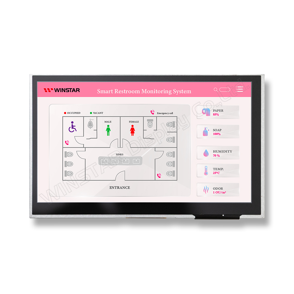
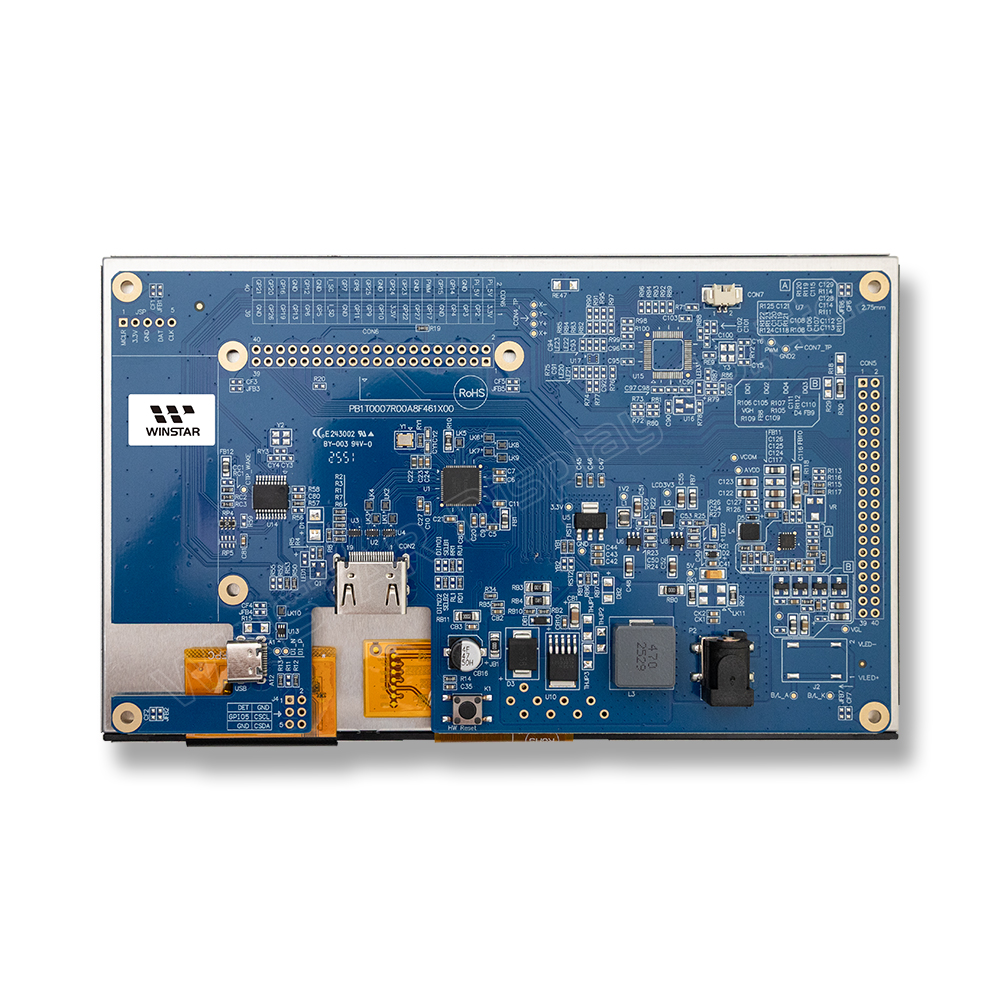
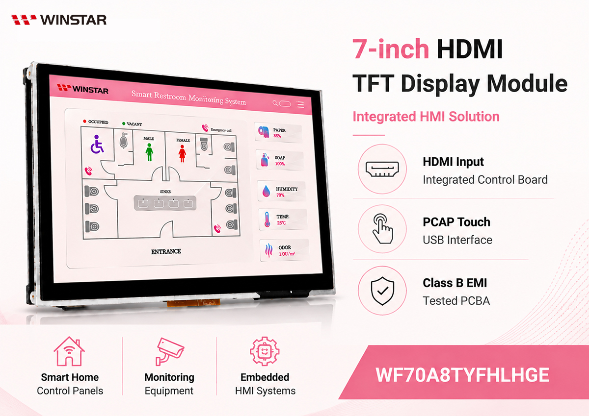
WF70A8TYFHLHGE is a 7-inch HDMI TFT LCD display module featuring a 1024 x 600 resolution, IPS technology, and a projected capacitive touch panel (PCAP). The module integrates a control board with the LT6911C controller IC and features an HDMI connector supporting DVI signal input, providing a convenient display solution for embedded system integration.

The 7-inch TFT display provides a typical brightness of 450 cd/m² and an 85/85/85/85-degree viewing angle. The integrated PCAP touch panel uses the ILI2130 controller IC with a USB interface and supports 1-point touch as standard, with 2-point or other touch options available upon request. The module measures 169.9 x 103.4 x 23.9 mm, with an active area of 154.2144 x 85.92 mm. It operates within a temperature range of -20°C to +70°C and can be stored from -30°C to +80°C.

PCBA Tested for Class B EMI Performance

Electromagnetic interference (EMI) is an important consideration when integrating display modules into electronic systems. To address EMI performance at the board level, the integrated PCBA of WF70A8TYFHLHGE has undergone third-party EMI testing and passed Class B level requirements. This provides system developers with a display platform whose PCBA EMI performance has been evaluated during product development, helping support integration into applications where electromagnetic compatibility is an important design consideration.

Applications

With its integrated control board, HDMI connector, USB PCAP touch interface, and tested PCBA EMI performance, WF70A8TYFHLHGE is suitable for smart home systems, security monitoring equipment, bathroom control and display panels, home entertainment systems, storage management systems, and other embedded HMI applications.

DRAWING

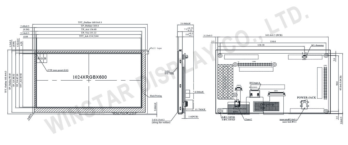
WF70A8TYFHLHGE - Contour Drawing

SPECIFICATIONS

General Specifications

Item Dimension Unit
Size 7.0 inch
Dot Matrix 1024 x RGB x 600(TFT) dots
Module dimension 169.9(W) x 103.4(H) x 23.9(D) mm
Active area 154.2144 x 85.92 mm
Dot pitch 0.1506 x 0.1432 mm
LCD type TFT, Normally Black, Transmissive
Viewing Angle 85/85/85/85
Aspect Ratio 16:9
Controller IC LT6911C or equivalent
Backlight Type LED, Normally White
TFT Interface DVI
CTP IC ILI2130 or Equivalent
CTP Interface USB
CTP FW Version 0x07.0x00.0x00.0x00.0x65.0x90.0x00.0x01
CTP Resolution 16384*16384
Touch Panel Projected capacitive touch panel (PCAP)
Surface Glare

Absolute Maximum Ratings

Item Symbol Min Typ Max Unit
Operating Temperature TOP -20 +70
Storage Temperature TST -30 +80

Electrical Characteristics

Operating conditions

Item Symbol Condition Min Typ Max Unit
Supply Voltage For LCM VDD 4.9 5 5.1 V
Supply Current For LCM IDD 1470 2205 mA
LED life time 50,000 Hr
 

Backlight conditions:

Parameter Symbol Min. Typ. Max. Unit
PWM Control Level (Backlight PWM) High Level - 3.3 - V
Low Level - 0 - V
PWM Control Frequency - - 1K - Hz

Interface

1. USB

Pin No Symbol Function
A1 GND Power Ground
A4 NC No connection
A5 NC No connection
A6 D+ Data line +
A7 D- Data line -
A8 NC No connection
A9 NC No connection
A12 GND Power Ground
B12 GND Power Ground
B9 NC No connection
B8 NC No connection
B7 D- Data line -
B6 D+ Data line +
B5 NC No connection
B4 NC No connection
B1 GND Power Ground
 

2. POWER JACK

Pin No. Symbol Function
1 5V Power Supply (5V)
2 GND Ground
3 NC No connection
 

3. B/L dimming

Pin No. Symbol Function
1 PWM Light Dimming Control (PWM) Input Voltage (bright in 0% ;dark in 100%)
2 GND Ground
 

4. DVI

Pin No. Symbol I/O Function
1 Rx2+ I Channel-2 positive receiver input; low-voltage signal differential- input pair.
2 GND P Ground
3 Rx2- I Channel-2 negative receiver input; low-voltage signal differential- input pair.
4 Rx1+ I Channel-1 positive receiver input; low-voltage signal differential- input pair.
5 GND P Ground
6 Rx1- I Channel-1 negative receiver input; low-voltage signal differential- input pair.
7 Rx0+ I Channel-0 positive receiver input; low-voltage signal differential- input pair.
8 GND P Ground
9 Rx0- I Channel-0 negative receiver input; low-voltage signal differential- input pair.
10 RxC+ I Clock positive receiver input; low-voltage signal differential- input pair.
11 GND P Ground
12 RxC- I Clock negative receiver input; low-voltage signal differential- input pair.
13-14 NC - No connection
15 SCL I/O DDC(Data Display Channel) Clock
16 SDA I/O DDC(Data Display Channel) Data
17 GND P Ground
18 5V P Power Supply
19 Detect I/O Hot plug detect
I: input, O: output, P: Power
go top
close

We value your privacy

By clicking "Allow All Cookies", you agree to the storing of cookies on your device to enhance site navigation, analyse site usage, and assist in our marketing and performance efforts. You can find further information this subject in our policy.

We value your privacy

Winstar and certain third parties use cookies on www.winstar.com.tw. The details regarding the types of
cookies, their purpose and the third parties involved are described below and in our Cookie Policy.
Please click on “Allow All” to consent to our usage of cookies in order to have the best possible
experience on our websites. You can also set your preferences or reject cookies (except for strictly
necessary cookies).

Manage Consent Preferences

Always Active
Essential Cookies

These cookies are essential in order to enable you to move around the website and use its
features, such as setting your privacy preferences, logging in or filling in forms.

Analytics Cookies

Also known as “statistics cookies,” these cookies collect information about how you use a website, like which pages you visited and which links you clicked on. See Detail