This article provides an overview of the MIPI CSI-2 camera interface, covering system architecture, D-PHY transmission, packet mechanisms, image formats, and bandwidth estimation, as well as integration and troubleshooting within the Linux media-controller framework. The content is intended for hardware and software integration involving ARM-based SoCs, image sensors, ISPs, and V4L2 video pipelines.
MIPI CSI System Architecture
MIPI CSI-2 (Camera Serial Interface 2) is a high-speed serial protocol used to transfer image data from an image sensor to a SoC, ISP, or FPGA. CSI-2 defines packet formats, Data Types, Virtual Channels, and error protection mechanisms, while D-PHY or C-PHY provides physical signal transmission.
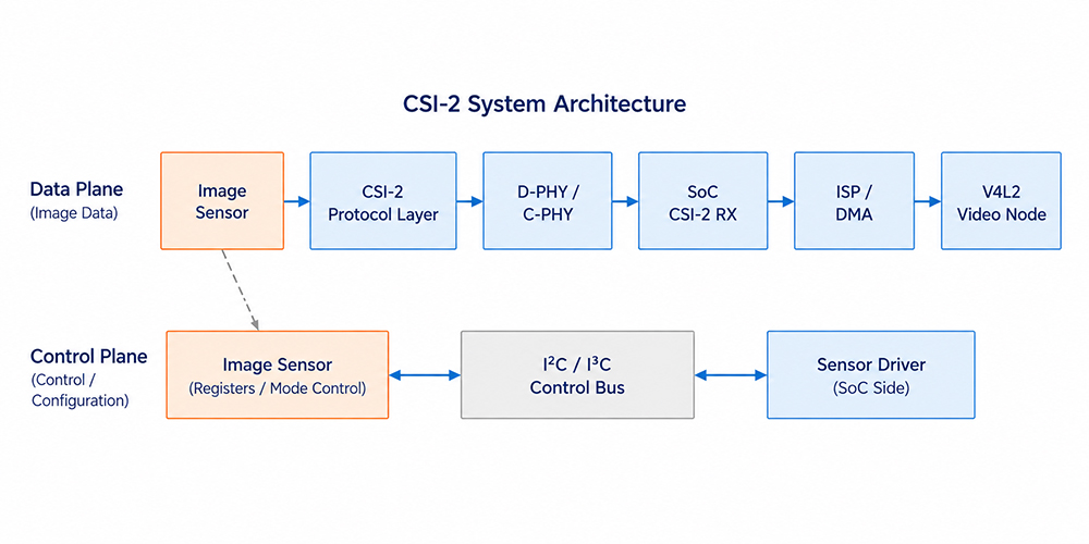
| Layer |
Primary Responsibility |
Typical Linux / SoC Implementation |
| Control Plane |
Mode, exposure, gain, and stream control |
Sensor driver and I²C/I³C |
| CSI-2 Protocol Layer |
Packetization, VC, DT, ECC, and CRC |
CSI-2 TX/RX controller |
| PHY Layer |
LP/HS states, clocking, and differential signaling |
D-PHY/C-PHY and PHY driver |
| Image Pipeline |
Decoding, processing, DMA, and capture |
ISP, DMA, and V4L2 node |
D-PHY Transmission and Timing
When idle, a D-PHY Data Lane remains in the LP Stop State and transitions through the LP state sequence into HS mode before transmitting CSI-2 packets. Sensor register access and stream control are typically handled over a separate I²C/I³C bus, which is distinct from the LP states of the D-PHY Data Lane.
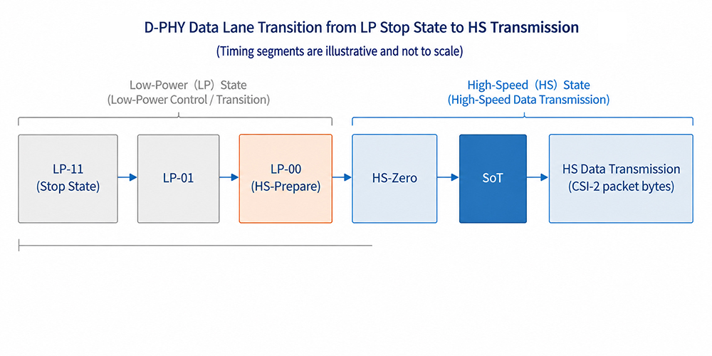
| State / Phase |
Function |
Integration Considerations |
| LP-11 Stop State |
Idle state and basis for LP operation |
Verify the lane state and TX/RX PHY support |
| LP-01, LP-00 |
Part of the HS entry/exit sequence |
Do not interpret these states as I²C control data |
| HS-Prepare, HS-Zero |
Preparation and stabilization before high-speed transmission |
Affects RX detection and HS-Settle tuning |
| SoT |
Marks the start of high-speed packet transmission |
SoT errors may indicate timing, lane, or configuration issues |
| HS data transmission |
Transfers the CSI-2 packet byte stream |
Verify link frequency, lane count, and signal integrity |
- In clocked mode, the Clock Lane supports receiver sampling during HS transmission. Continuous or non-continuous clock operation should be verified according to the image sensor, SoC PHY, and driver configuration.
- HS-Settle should be tuned based on the actual link frequency, SoC receiver documentation, and error counters; a higher value is not necessarily better.
CSI-2 Packets and Synchronization
CSI-2 uses Short Packets to carry protocol events or synchronization information, while Long Packets carry RAW, YUV, RGB, or embedded data. A Long Packet consists of a 4-byte header, a payload, and a 2-byte CRC footer.
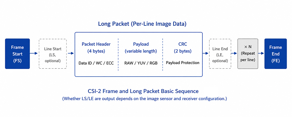
| Field |
Function |
Items to Check |
| Virtual Channel (VC) |
Distinguishes logical data streams |
The sensor and RX Virtual Channel must be compatible |
| Data Type (DT) |
Identifies the pixel format or packet type |
Must match the sensor output mode and RX capabilities |
| Word Count (WC) |
Specifies the Long Packet payload length in bytes |
Should correspond to the line width and pixel packing |
| ECC |
Protects the packet header |
Check synchronization, lane, configuration, and RX decoding |
| CRC |
Protects the Long Packet payload |
Check the PHY, data rate, lane mapping, and TX/RX implementation |
Frame Start (FS) and Frame End (FE) provide frame-level synchronization. Line Start (LS) and Line End (LE) provide optional line-level synchronization. Whether LS and LE are actually transmitted should be verified against the image sensor documentation, CSI receiver traces, or driver counters.
Image Formats and Bandwidth
CSI-2 Data Types, V4L2 media-bus codes, V4L2 capture memory formats, and ISP format negotiation must represent compatible image data, although they belong to different abstraction layers and their configuration names and locations do not need to correspond one-to-one. For RAW data, verify both the bit depth and Bayer order; for YUV data, verify the byte order.
The minimum active-pixel payload can be estimated as follows:
Active-pixel payload = Width × Height × FPS × Bits per pixel
This calculation represents only the minimum payload required for active pixel data. Actual CSI-2 throughput and D-PHY lane rate must also account for packet headers, CRC, synchronization packets, the blanking transmission strategy, the number of Data Lanes, clock mode, available sensor link-frequency settings, and the limitations of the SoC CSI receiver.
Per-lane rate ≳ Total CSI-2 throughput / Number of Data Lanes
Linux Integration and Bring-up
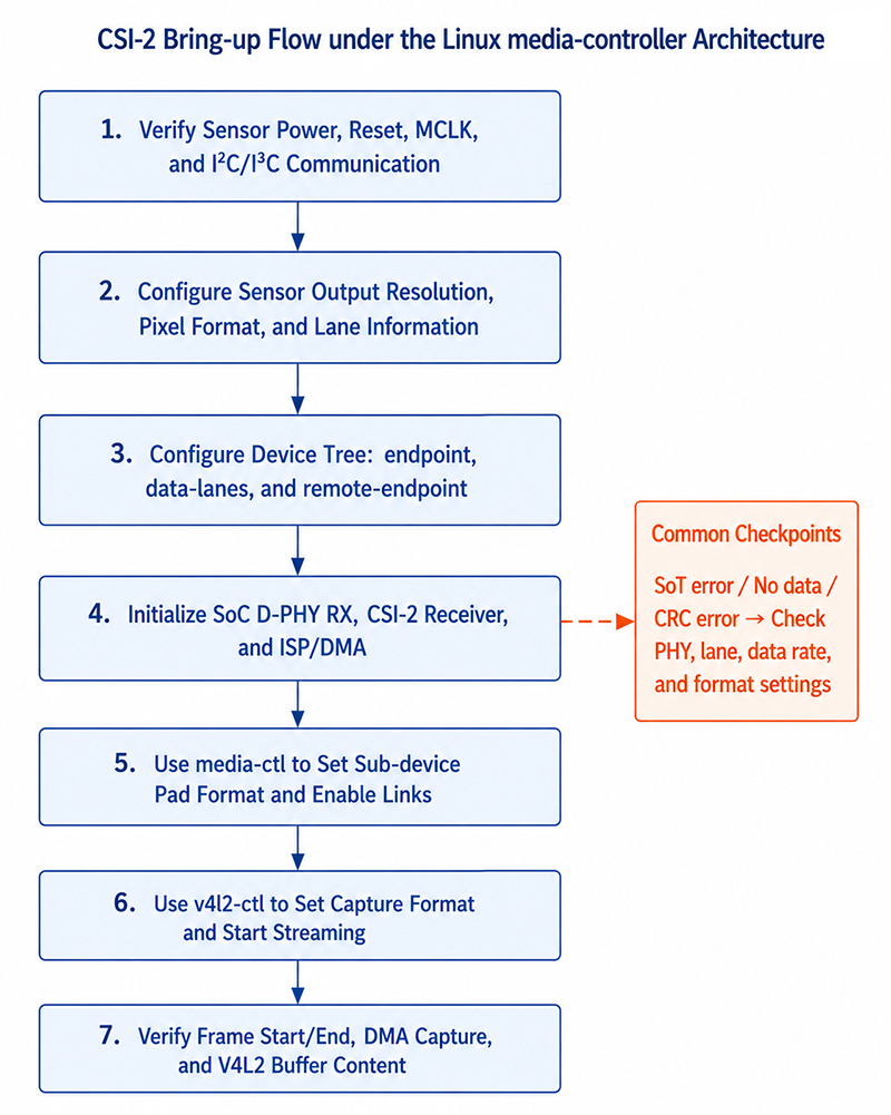
The Device Tree typically describes graph endpoints, data-lanes, clock-lanes, and remote-endpoint connections. In most media-controller architectures, image formats are negotiated at runtime through sub-device pad formats, media links, and routing negotiation. The actual bindings and supported formats depend on the kernel driver for the target SoC.
# Inspect entities, pads, and links
media-ctl -p -d /dev/media0

# Example: Configure the upstream sensor pad format
media-ctl -d /dev/media0 --set-v4l2 '"sensor 1-001a":0 [fmt:SRGGB10_1X10/1920x1080]'

# Example: Enable the link
media-ctl -d /dev/media0 --links '"sensor 1-001a":0 -> "csi2rx":0 [1]'

# Configure the capture node memory format and start streaming
v4l2-ctl -d /dev/videoX \
  --set-fmt-video=width=1920,height=1080,pixelformat=RG10 \
  --stream-mmap=4 --stream-count=100

dmesg -w
The entity names, pad indexes, media-bus codes, FourCC values, and video nodes shown in this example must be adjusted to match the actual media graph and are not fixed across platforms.
Compatibility and Error Analysis
| Area |
Items to Check |
Typical Symptoms |
| PHY |
Lane count, mapping, link frequency, clock mode, and HS-Settle |
SoT errors, no data, or intermittent frame drops |
| Protocol |
VC, DT, packet behavior, and ECC/CRC |
Header errors, CRC errors, or frame synchronization issues |
| Format |
Bit depth, Bayer order, YUV order, and packing |
Incorrect colors, green frames, or corrupted images |
| Pipeline |
DT graph, media links, pad formats, ISP, and DMA |
STREAMON failure or buffer timeout |
- If I²C communication is working but no image is received, check power/reset/MCLK, sensor stream-on status, data-lanes, lane mapping, link frequency, the media graph, and CSI RX status.
- If frame activity is detected but ECC/CRC errors occur, check the RX error counters, lane mapping, link rate, HS-Settle, board-level signal integrity, and TX/RX configuration.
- If frames can be captured but the colors are incorrect, check the RAW bit depth, Bayer order, media-bus code, memory FourCC, and ISP pipeline.
Frequently Asked Questions
1. Are CSI-2 and D-PHY the same?
No. CSI-2 is an image packet protocol, while D-PHY is a commonly used physical-layer transmission interface.
2. Why is there no image even though I²C communication is working?
Successful I²C communication only confirms the control channel. The image data path may still be affected by issues with MCLK, lanes, PHY timing, the protocol, the media graph, ISP, or DMA.
3. What is the difference between ECC and CRC?
ECC primarily protects the Packet Header and can correct single-bit errors and detect two-bit errors. CRC verifies the integrity of the Long Packet payload. Persistent errors typically require checking both protocol configuration and physical-layer signal integrity.
4. Why can the same image sensor behave differently on different boards?
PCB impedance, trace length, FPC, ground return paths, and EMI conditions can all affect D-PHY signal integrity and timing margin.
References
- MIPI Alliance, "Camera Serial Interface 2 (MIPI CSI-2)", mipi.org/specifications/csi-2
- MIPI Alliance, "MIPI D-PHY", mipi.org/specifications/d-phy