


Chip-on-Glass LCD Module 16x2
Model No. WO1602F
►COG LCD 16x2
►Character LCD
►5 x 8 dots includes cursor
►IC: ST7032
►1/16 duty, 1/5 bias
►5V power supply
►Interface : 6800/SPI/I2C
Description
The WO1602F series is a COG (Chip-on-Glass) Character LCD display module built with an ST7032 IC. It supports 6800/4-Line SPI and I2C interfaces, featuring a display format of 16 characters x 2 lines. The supply voltage for logic (VDD) can be selected as either 3V or 5V. It operates with a 1/16 duty cycle and 1/5 bias. Operating temperatures for this module range from -20℃ to +70℃, with storage temperatures ranging from -30℃ to +80℃.
The WO1602F COG LCD display module stands out with its ultra-compact and thin design, making it an ideal choice for various applications. Its versatility allows seamless integration into compact applications, industrial devices, as well as security, medical, and handheld devices.
Its compact form factor and thin profile make it particularly well-suited for environments where space is at a premium. The module's integration of COG technology, with the chip positioned behind the LCD, not only contributes to its slim design but also eliminates the need for external packaging. This not only saves valuable space but also enhances the overall performance and stability of the display.
The WO1602F is a reliable solution for industries demanding efficiency and precision. Whether integrated into industrial equipment or employed in medical devices, this COG LCD display module excels in providing clear and vibrant visual representation.
In addition to its technical advantages, the WO1602F series offers a range of LED backlight options in various colors, allowing for customization based on specific requirements. For those seeking a display module that combines space-saving features with enhanced performance and flexibility, the WO1602F COG LCD display module proves to be a compelling choice. Explore the possibilities and elevate your applications with this advanced and compact display solution. Feel free to contact us through our website for more information.
DRAWING
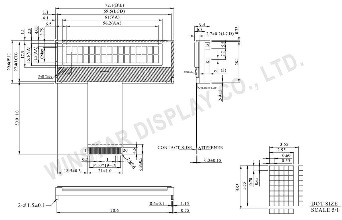
Data source ref:WO1602F-YYH-AT#
SPECIFICATIONS
Interface Pin Function
| Pin No. | Symbol | Level | Description | |||||||||||||||
|---|---|---|---|---|---|---|---|---|---|---|---|---|---|---|---|---|---|---|
| 1 | RS | H/L | Select registers. 0: Instruction register (for write) Busy flag & address counter (for read) 1: Data register (for write and read) |
|||||||||||||||
| 2 | R/W | H/L | Select read or write (In parallel mode). 0: Write 1: Read |
|||||||||||||||
| 3 | E | H,H→L | Starts data read/write. (“E” must connect to “VDD” when serial interface is selected.) | |||||||||||||||
| 4 | DB0 | H/L | Data bus line | |||||||||||||||
| 5 | DB1 | H/L | Data bus line | |||||||||||||||
| 6 | DB2 | H/L | Data bus line | |||||||||||||||
| 7 | DB3 | H/L | Data bus line | |||||||||||||||
| 8 | DB4 | H/L | Data bus line | |||||||||||||||
| 9 | DB5 | H/L | Data bus line | |||||||||||||||
| 10 | DB6/SCL | H/L | Data bus line (In I2C interface DB6 (SCL) is clock input. SDA and SCL must connect to I2C bus (I2C bus is to connect a resister between SDA/SCL and the power of I2C bus ). |
|||||||||||||||
| 11 | DB7/SDA | H/L | Data bus line (In I2C interface DB7 (SDA) is input data. SDA and SCL must connect to I2C bus (I2C bus is to connect a resister between SDA/SCL and the power of I2C bus ). |
|||||||||||||||
| 12 | VSS | 0V | Ground | |||||||||||||||
| 13 | VDD | 3.3/5.0V (bon=1 Max=3.5V |
Supply Voltage for logic | |||||||||||||||
| 14 | Vout | (Variable) | Operating voltage for LCD | |||||||||||||||
| 15 | PSB | Interface selection 0:serial mode (“E” must connect to “VDD” when serial mode is selected.) 1:parallel mode(4/8 bit) In I2C interface PSB must connect to VDD |
||||||||||||||||
| 16 | PSI2B |
|
||||||||||||||||
| 17 | CAP1P | For voltage booster circuit(VDD-VSS) External capacitor about 0.1u~4.7uf |
||||||||||||||||
| 18 | CAP1N | |||||||||||||||||
| 19 | NC | No connection | ||||||||||||||||
| 20 | NC | No connection |
Mechanical Data
| Item | Dimension | Unit |
|---|---|---|
| Number of Characters | 16 characters × 2Lines | - |
| Module dimension | 72.1 × 29.6 × 9.4 | mm |
| View area | 61.0 × 15.1 | mm |
| Active area | 56.2 × 11.5 | mm |
| Dot size | 0.55 × 0.65 | mm |
| Dot pitch | 0.60 × 0.70 | mm |
| Character size | 2.95 × 5.55 | mm |
| Character pitch | 3.55 × 5.95 | mm |
| Duty | 1/16 , 1/5 Bias | |
| Backlight Type | LED | |
| IC | ST7032i | |
| Interface | 68/ 4-Line SPI /IIC | |
Absolute Maximum Ratings
| Item | Symbol | Min | Typ | Max | Unit |
|---|---|---|---|---|---|
| Operating Temperature | TOP | -20 | - | +70 | ℃ |
| Storage Temperature | TST | -30 | - | +80 | ℃ |
| Input Voltage | VIN | -0.3 | - | VDD+0.3 | V |
| Power Supply Voltage | VDD-VSS | -0.3 | - | +6.0 | V |
| LCD Driver Voltage | VLCD | 2.7 | - | 7.0 | V |
Electrical Characteristics
| Item | Symbol | Condition | Min | Typ | Max | Unit |
|---|---|---|---|---|---|---|
| Supply Voltage For Logic | VDD-VSS | - | 3 | 3.3 | 5 (bon=1 max=3.5V) |
V |
| Supply Voltage For LCD | Vout-VSS | Ta=-20℃ Ta=25℃ Ta=70℃ |
4.3 - |
- 4.5 - |
- 4.7 - |
V V V |
| Input High Volt. | VIH | - | 0.7 VDD | - | VDD | V |
| Input Low Volt. | VIL | - | - | - | 0.2 VDD | V |
| Output High Volt. | VOH | - | 0.8 VDD | - | VDD | V |
| Output Low Volt. | VOL | - | - | - | 0.2VDD | V |
| Supply Current | IDD | - | - | - | 2.0 | mA |
Search Keyword: lcd 16x2, lcd 16 x 2, 16x2 lcd, 16 x 2 lcd, 16x02 lcd, lcd 16x02
