


7 inch CAN Bus High Brightness TFT Display with Projected Capacitive Touch
Model No. WL0F0007000A8GAAASA01
►TFT Size: 7"
►TFT Resolution: 1024×600 dots
►TFT View Direction: 85/85/85/85 (IPS)
►Communication Interface: CAN bus
►Protocol: CANopen
►TFT Touch Screen: Capacitive Touch Panel
►Brightness(cd/m²): 850
Description
WL0F0007000A8GAAASA01 is a 7" Smart Display_CAN series TFT which is defined as a slave device, that is controlled by master device via CAN bus command to render display content on the display screen and return touch event data with protocol objects. WL0F0007000A8GAAASA01 is integrated with a high brightness IPS TFT module WF70A8SYAHLNGB and 4-layers PCBA with built-in firmware. This 7" Smart Display _CAN series TFT is an easy-to-use product which allows customers to develop projects rapidly in cost-effective way. This 7" Smart Display can use computer with USB2CAN dongle or Raspberry Pi interface (PiCAN2) as HOST platform.
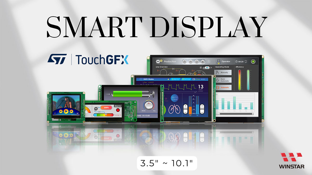
Smart Display products are designed with STMicroelectronics' (ST) controller which supports ST development tools like TouchGFX and STM32CubeIDE. You can also use ST tools to design WINSTAR Smart Display modules besides GUI builder.
- TouchGFX: An advanced free-of-charge graphic software framework optimized for STM32 microcontrollers.
- STM32CubeIDE: An advanced C/C++ development platform with peripheral configuration, code generation, code compilation, and debug features for STM32 microcontrollers and microprocessors.
- STM32CubeMX: A graphical tool that allows a very easy configuration of STM32 microcontrollers, as well as the generation of the corresponding initialization C code for the Arm® Cortex®-M core or a partial Linux® Device Tree for Arm® Cortex®-A core, through a step-by-step process.
- STM32CubeProg: An all-in-one multi-OS software tool for programming STM32 products. It provides an easy-to-use and efficient environment for reading, writing and verifying device memory through both the debug interface (JTAG and SWD) and the bootloader interface (UART, USB DFU, I2C, SPI, and CAN).
We’ve also pushed the sample code on Github for your ST platform design reference: ► Link to Github
Below are the features of 7" smart display:
- +12V power supply input with 5V to 16V dynamic range power input, the power consumption is around 8 WATT.
- Self testing after booting function.
- CAN bus communication interface.
- Supports CANopen protocol, default baud rate at 250KB.
- Built in flash memory, storing the font and Object Dictionary Data.
- Supports projected capacitive touch screen (PCAP).
- Embedded buzzer controlled by Master Device.
- HOST can be used on multiple platforms, such as Computer (with USB to CAN Dongle), MCU, Raspberry Pi (with PiCAN2).
- Design the UI without writing a line of code by WINSTAR GUI builder! (►Link to GUI Builder Introduction)
- Designed with STM32F series MCU and Support STMicroelectronics' (ST) software development tools.
Try before you buy! Contact us to download WINSTAR GUI Builder application.
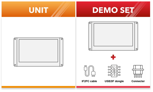
We also provide demo set with all needed accessories for you to realize your GUI design on displays.
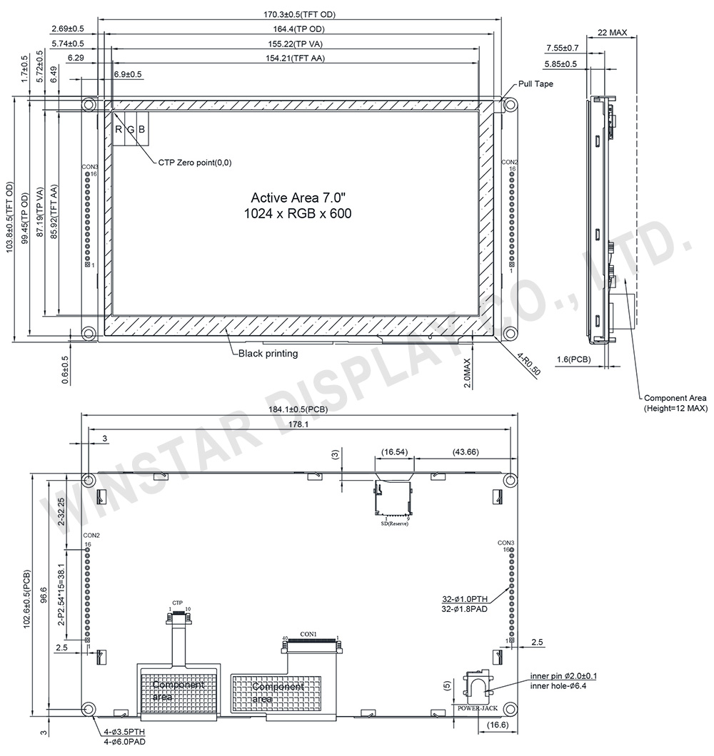
DRAWING
SPECIFICATIONS
General Specifications
| Item | Standard Value | Unit |
|---|---|---|
| Operating voltage | 5~16V | Vdc |
| Communication Interface | CAN bus differential ± 3.3 | Vpp |
| MCU | STM32F746 | N/A |
| Flash Memory | 16 | MB |
| SDRAM Frequency | 108 | MHz |
| LCD display size | 7.0 | inch |
| Dot Matrix | 1024 x RGB x 600(TFT) | dot |
| Module dimension | 184.1(W) x 103.8(H) x 22(D) | mm |
| Active area (AA) | 154.2144 x 85.92 | mm |
| Dot pitch | 0.1506 x 0.1432 | mm |
| Brightness | Min: 800; Typ: 850 | cd/m2 |
| LCD type | TFT, Normally Black, Transmissive | |
| View Direction | 85/85/85/85 | |
| Aspect Ratio | 16:9 | |
| Touch Panel | With Projected Capacitive Touch Panel (PCAP) | |
| Surface | Glare | |
Absolute Maximum Ratings
| Item | Symbol | Min | Typ | Max | Unit |
|---|---|---|---|---|---|
| Operating Temperature | TOP | -20 | - | +70 | ℃ |
| Storage Temperature | TST | -30 | - | +80 | ℃ |
Electrical Characteristics
| Item | Symbol | Condition | Min | Typ | Max | Unit |
|---|---|---|---|---|---|---|
| Supply Voltage | VIN | - | 5 | 12 | 16 | V |
| Supply current | I(mA) | - | - | 675 | - | mA |
Bom
| Item | Description |
|---|---|
| LCM | WF70A8SYAHLNGB# |
| PCBA | SV10007R00AAA00N0105 |
Interface Pin Function
CON2 definition
| Pin | Symbol | Function |
|---|---|---|
| 1 | VIN | Power supply V+ |
| 2 | GND | Power supply GND input |
| 3 | CAN_H | CAN bus D+ |
| 4 | CAN_L | CAN bus D- |
| 5 | GND | Power supply GND input |
| 6 | GND | Power supply GND input |
| 7 | NC | - |
| 8 | NC | - |
| 9 | Reserve | - |
| 10 | Reserve | UART RX interface(Reserve) |
| 11 | Reserve | UART TX interface(Reserve) |
| 12 | GND | GND |
| 13 | Reserve | - |
| 14 | NC | - |
| 15 | NC | - |
| 16 | GND | GND |
CON3 definition
| Pin | Symbol | Function |
|---|---|---|
| 1 | VDD3V | 3.3V power for JTAG interface |
| 2 | JTAG_SWCLK | CLK pin for JTAG interface |
| 3 | GND | GND for JTAG interface |
| 4 | JTAG_SWDIO | Data pin for JTAG interface |
| 5 | NRST | Reset pin for JTAG interface |
| 6 | GND | GND |
| 7~16 | NC | - |
