Winstar offers a wide range of standard Character LCD Modules for customer's application. Available standard display types are WH0802, WH1202, WH1601, WH1602, WH1604, WH2002, WH2004, WH2402 and WH4002 series. Customer can use the least number of control pins to achieve display, making it easier for choosing a MCU.
The common Character LCD Modules in the market will add a transfer board to support I2C interface as figure 1 shows, which lead to the increase of LCM thickness, more processes in manufacturing and the lower yield rate.
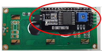
Figure 1: The common Character LCD Module in the market which adds a transfer board to support I2C.
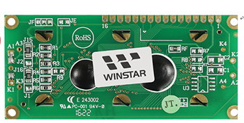
Figure 2: Winstar's WH1602 Character LCD Module supports I2C and SPI interface without an additional transfer board.
Without adding a transfer board, Customer just need to connect the development board Arduino Uno and can use different communication interface to control the following Winstar’s Character LCD Modules directly.
- WINSTAR WH1602 LCM: 16 characters by 2 lines
- WINSTAR WH2002 LCM: 20 characters by 2 lines
- WINSTAR WH2004 LCM: 20 characters by 4 lines
These three LCM series built in RW1063 LCD controller which supports serial interface (I2C and SPI) and parallel interface (6800)
Note: For more information about display interfaces, please refer to "Getting to Know Display Interfaces" .
Identify the LCM's pin define
| Pin No. |
Symbol |
Description |
| No.1 |
Vss |
Ground |
| No.2 |
Vdd |
Power supply for logic |
| No.3 |
V0 |
Contrast Adjustment |
| No.4 |
RS |
Command/data selection |
| No.5 |
RW |
Read/Write select signal for interface 6800 8/4bit only |
| No.6 |
E |
Enable signal for interface 6800 8/4bit only |
| No.7 |
DB0/SA0 |
Data bus line 0 for 6800 8bit interface only
SA0 address setting line for I2C interface |
| No.8 |
DB1/SA1 |
Data bus line 1 for 6800 8bit interface only
SA1 address setting line for I2C interface |
| No.9 |
DB2 |
Data bus line 2 for 6800 8bit interface only |
| No.10 |
DB3 |
Data bus line 3 for 6800 8bit interface only |
| No.11 |
DB4 |
Data bus line 4 for 6800 8/4bit interface only |
| No.12 |
DB5/CSB/CSB |
Data bus line 5 for 6800 8/4bit interface only
CSB enable selection lines for I2C & SPI interface |
| No.13 |
DB6/SDA/SCLK |
Data bus line 6 for 6800 8/4bit interface only
SDA data line for I2C interface
SCLK timing for SP Interface |
| No.14 |
DB7/SCL/SID |
Data bus line 7 for 6800 8/4bit interface only
SCL timing line for I2C interface
SID data line for SPI interface |
| No.15 |
A+ |
Power supply for B/L + |
| No.16 |
K- |
Power supply for B/L - |
Table 1:LCM pin define
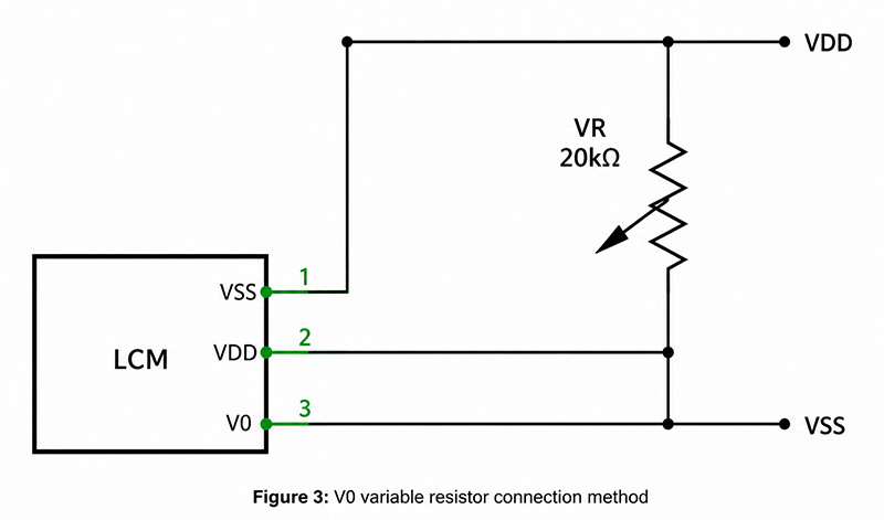
Regarding V0 in the above table, a 20k Ohm variable resistor is used to adjust the contrast of characters. If the text is invisible or it continues to display the background image during the test, please turn this variable resistor to adjust the contrast.
The connection method of V0 variable resistor as shown in Figure 3:
Figure 3:V0 variable resistor connection method
How to connect LCM and development board Arduino Uno
The connection methods of four LCM communication interfaces (I2C, SPI, 6800 8bit/4bit) to Arduino Uno as shown in Figure 4. The users can observe that the I2C and SPI interfaces only need a small number of GPIO pins to control the Character LCD modules.
For I2C interface, since Arduino Uno provides the pull-up resistors inside the I2C pins, there are no additional pull-up resistors connected to SDA and SCL pins. If the internal pull-up resistor is disabled in the program, an external pull-up resistor must be connected.
(a) I2C interface connection
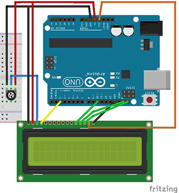
(b) SPI interface connection
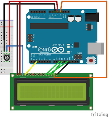
(c) 6800-4bit interface connection
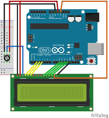
(d) 6800-8bit interface connection
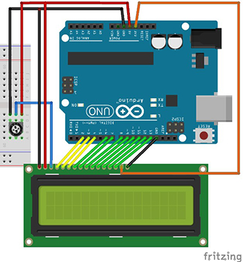
Figure 4: Connection methods of four LCM communication interfaces to Arduino Uno.
LCM Commands
Not every communication interface can use the full command set of LCM; with SPI interface, there is no RW control line and MISO pins, therefore, the read command is not supported. For writing, through RS control line to determine whether to write command data or display data.
In the I2C interface, there is also no RW control line so there is no support for read commands either. Before writing command data or display data, the command control code (A0=0) or data control code (A0=1) has to be sent to determine whether the next byte to be sent is command data or display data.
SPI and I2C Interface Timing
Two timing diagrams are shown in Figure 5 and Figure 6. It is the timing diagram of controlling the LCM through the SPI interface. The users can observe that the LCM uses an SPI that is not the typical SPI interface provided by a typical MCU, it requires an additional RS signal line to determine whether the current byte being sent is a command? or data? The bit data (BIT7~BIT0) of the data line (SID) changes when the clock line (SCLK) is at low level. The bit (BIT7~BIT0) data is captured when the clock line (SCLK) is high level (BIT7~BIT0).
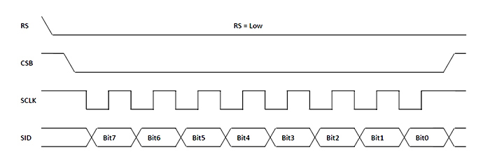
Figure 5:Timing of SPI write command
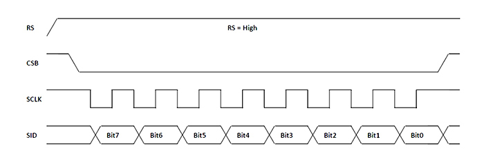
Figure 6:Timing of SPI write data
Figure 7 and 8 show the timing diagram of controlling the LCM through the I2C interface. Except for the chip select bar (CSB), readers can observe that the I2C interface control is to send three bytes each time to write a command data or display data. Among them, the A0 bit of the second byte will determine whether the third byte is command data or display data.
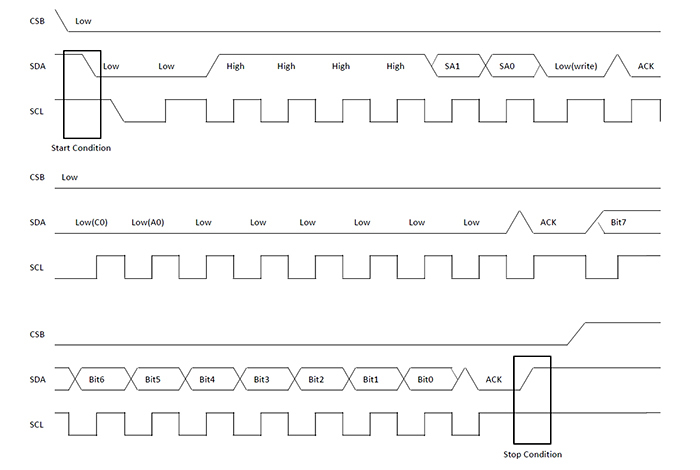
Figure 7:I2C Timing of writing commands
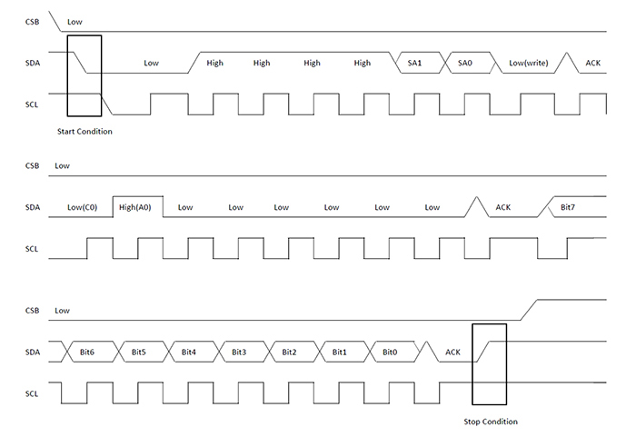
Figure 8:I2C Timing of writing data
Code
The LCM can be compiled and used directly by modifying the program settings.
Step1: set the maximum number of characters in a single line of LCM.
For example, the following sets a single line to have a maximum of 16 characters.

Step2: set the maximum number of lines in the LCM.
For example, the following sets the LCM to have 2 lines.

Step3: set the LCM interface.
For example, the following sets I2C interface.

Step4: compile and upload the program to the Arduino Uno development board.
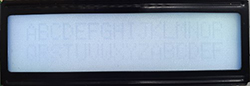
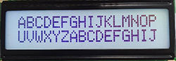
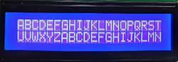
Figure 9 shows a schematic diagram of the screens of three LCMs.
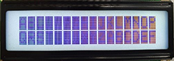
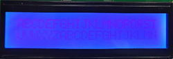
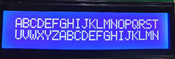
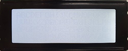
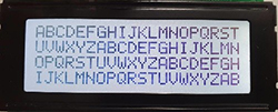
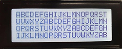
When the display contrast is light or dark, the variable resistor at the V0 pin can be adjusted to an appropriate contrast, as shown in Figure 10.
| (a) Light contrast Only light characters can be seen. |
(b) Appropriate contrast |
(c) Dark contrast Each character has an obvious shadow. |
 |
 |
 |
 |
 |
 |
 |
 |
 |
| Figure 9:a schematic diagram of the screens of three LCMs |
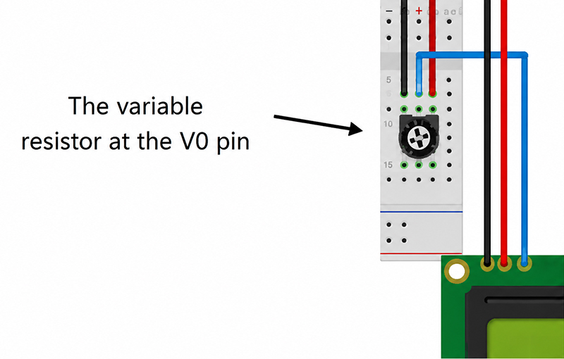
Figure 10:the V0 pin is adjustable
If you have demand of full demo code, please contact us.