The Smart Display UART protocol is a proprietary communication protocol developed by WINSTAR for communication and control between a host controller and WINSTAR Smart Displays via the UART interface. Together with WINSTAR GUI Builder, it provides a streamlined approach to HMI development, from user interface design to device communication and control.
With GUI Builder, developers can create HMI interfaces using a range of Widgets, from basic Buttons and Text to Gauges and Keypads, to meet different application requirements. This visual development approach simplifies UI design while providing greater flexibility for creating application-specific interfaces.
Once the user interface is created, the host controller can communicate with and control the Smart Display via UART using WINSTAR's proprietary communication protocol and commands. This integration of UI design and UART communication helps simplify HMI development and system integration.
WINSTAR continues to enhance GUI Builder to provide a more efficient and flexible development experience for Smart Display applications.
Smart Display GUI Builder – UART Project Setting Instructions
Smart Display GUI Builder provides an intuitive and user-friendly interface, allowing you to easily create your own HMI projects. Simply drag and drop various Widgets onto the page using GUI Builder, and you can easily display and interact with them on your Smart Display device. With simple operation and flexible functionality, it can meet various application needs and make your work more efficient.
The following steps introduce how to create a UART project using Smart Display GUI Builder and explain how to control objects through UART.
■ Create a UART Protocol Project
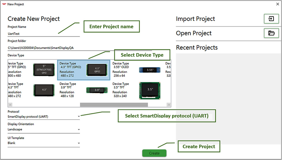
To create a UART project, enter the project name, select the Smart Display device type, and choose "SmartDisplay protocol (UART)" under the Protocol option based on your requirements.
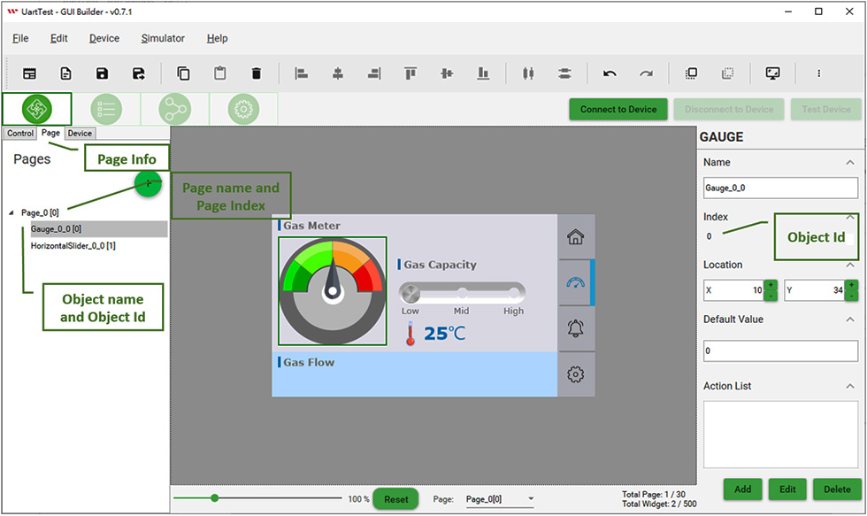
■ Add a Gauge and Horizontal Slider Widget to the Main Page
After adding a Widget, each object has a unique Index ID. Each object also has its Page Index and Object ID settings. With these two settings, the Host can control the object through UART commands.
■ Simulate the Interaction Between UART and the Widget
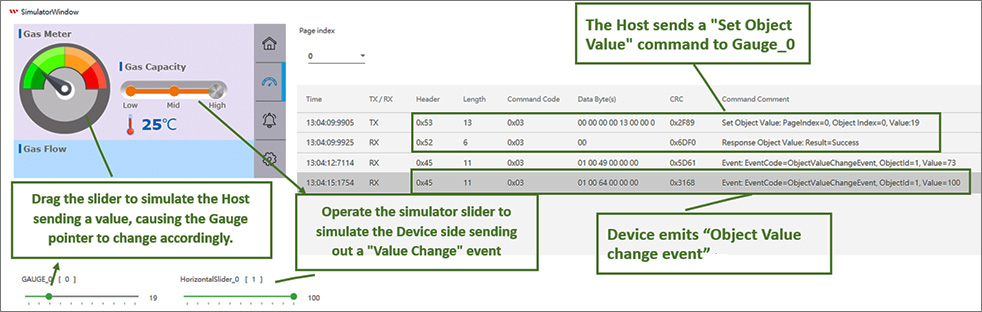
Click the "Simulator With GUI" icon to launch the simulator.

After launching the simulator, you can drag the slider labeled GAUGE_0 at the bottom to simulate the Host sending data to GAUGE_0. Observe the changes in the Gauge in the simulator and view the UART command log in the Message Log on the right. You can also interact with the Horizontal Slider in the simulator to simulate data being sent from the Device side.
■ Update the Smart Display Device Settings
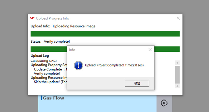
After verifying the functionality through the simulator, if everything is working correctly, you can connect to the device and upload the project settings to the Smart Display.
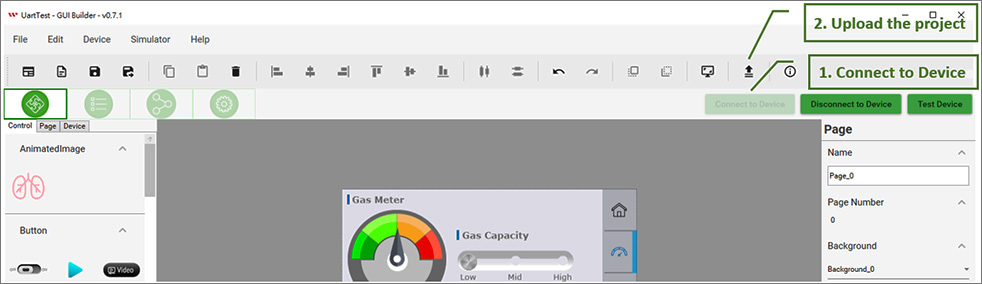
Wait for the upload and update process to complete.
■ Verify the Interaction Between the Device and the Widget
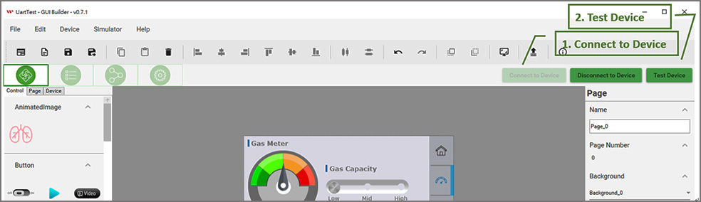
After uploading the project to the device, you can further verify the functionality on the Smart Display. Connect to the device using GUI Builder, click "Test Device," and then test the interaction between the Host and the Device.
■ Test Device Window
Through this testing interface, you can simulate the Host modifying the value of an object. Drag the slider labeled GAUGE_0 at the bottom to simulate the Host sending the value of Object 0. Observe the changes in the Gauge on the device. You can also view the Send command and Response command in the Message Log at the bottom. Additionally, interact with the Device's Horizontal Slider to confirm the Event command sent from the Device side.
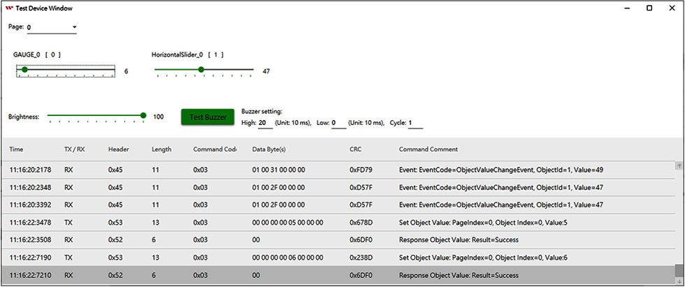
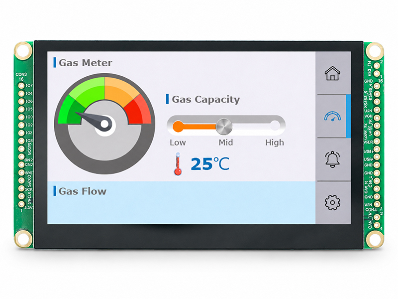
Through the Test Device window described above, you can simulate the Host sending UART commands to control the Smart Display. Observe the results on the Smart Display and operate the Smart Display through the Touch Panel to confirm that the Host receives the Event command.
Smart Display GUI Builder – Custom Widget
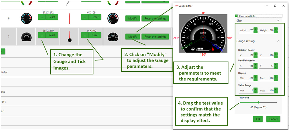
When the default Widgets in Smart Display GUI Builder do not meet the design requirements, customers can create custom Widget icons by replacing the corresponding images to achieve a customized interface. For simple buttons or toggle buttons, customization can be achieved by changing the On/Off images. For more complex Widgets, additional parameter settings may be required in addition to image replacement to ensure that the Widget is displayed correctly.
■ Custom Gauge Explanation and Example
You can create a custom Gauge by changing the images and adjusting the Gauge parameters accordingly.
■ Multilingual Text
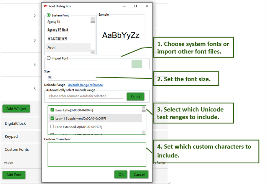
The Smart Display Text Widget supports Unicode, enabling the display of multilingual text. Follow the steps below to configure the text for different languages.
1. Add a Custom Font, select the desired font and size, and choose the Unicode text range to be displayed (you can refer to Unicode Character Blocks to confirm the Unicode range). If the required character range is too large, such as for Chinese characters, and there is insufficient Flash space, you can reduce the font storage requirements by including only the required characters in the Custom Characters section.
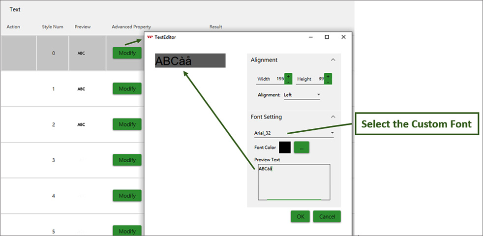
2. Set the font for the Text Widget: Select the Text Widget whose font settings you want to modify.
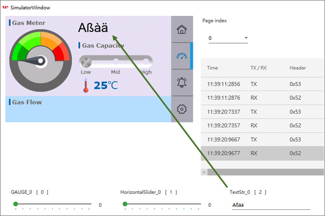
3. Add a Text Widget and verify in the simulator that the text is displayed correctly.
Introduction to Custom UART Commands
Next, we will introduce the UART command protocol. These commands allow the Host to control the Smart Display, including switching pages, adjusting the backlight brightness, and activating the buzzer.
The following are the default UART settings:
Default baud rate: 115200 (Can be modified through GUI Builder)
Parity Bit: None
Data Bit: 8
Stop Bit: 1
The main data format for UART is as follows:
| Header Byte(1 Byte) |
Length(1 Byte) |
Payload(N Byte) |
CRC(2 Byte) |
| Command Header |
Value: 4 + Payload length
Payload max size: 250 |
Payload data max size: 250 |
Modbus CRC16
(Calculate Modbus CRC16
https://www.modbustools.com/modbus_crc16.html) |
The UART protocol mainly has three major types of commands: Send command, Response command, and Event Command, with the following formats in order.
1. Send Command format
The Send command is used for the Host side to send commands to the SmartDisplay side.
| Header Byte(1 Byte) |
Length(1 Byte) |
Payload(N byte) |
CRC(2 Byte) |
| Start with 0x53 (S) |
Value: 4 + Payload length
Payload max size: 250 |
Command code: 1 byte
Command parameter: 0 ~ N bytes |
Modbus CRC16 |
2. Response command format
The Response command is used for the SmartDisplay side to reply to the Host side with the results of the Send command.
| Header Byte(1 Byte) |
Length(1 Byte) |
Payload(N byte) |
CRC(2 Byte) |
| Start with 0x52 (R) |
Value: 4 + Payload length
Payload max size: 250 |
Command Code: 1 byte
Error Code: 1 byte
Response Data: 0 ~ N bytes |
Modbus CRC16 |
3. Event Command
When the SmartDisplay side needs to proactively report data, it will use this command, for example, when a Button is triggered.
| Header Byte(1 Byte) |
Length(1 Byte) |
Payload(N byte) |
CRC(2 Byte) |
| Start with 0x45 (E) |
Value: 4 + Payload length
Payload max size: 250 |
Event Command Code: 1 byte
Event Data: 0 ~ N bytes |
Modbus CRC16 |
* For detailed Send Command code and Event Command code, please refer to the SmartDisplay UART User Guide document.
■ Explanation and examples of the Send/Response Command protocol
The following sequentially outlines the data format and examples for each command payload.
● Set Object Value: 0x3
Send Command
| Command Code |
1 Byte |
0x3 |
| Parameter data |
8 Byte |
uint16 PageIndex;
uint16 ObjectId;
int32 value; |
Response command
| Command Code |
1 Byte |
0x3 |
| Error Code |
1 Byte |
0: Success
1: Failed |
Example: Set Object value

● Set Object Buffer Data: 0x5
Send Command
| Command Code |
1 Byte |
0x5 |
| Parameter data |
N Byte |
uint16 PageIndex;
uint16 ObjectId;
uint8 [] data (max 100 bytes)
// Unicode String for Text
// Clock setting for Digital Clock |
Response command
| Command Code |
1 Byte |
0x5 |
| Error Code |
1 Byte |
0: Success
1: Failed |
Example: Set Object Text: test

Example: Set Clock Widget date time: 2024/09/01 04:05:06

● Set Brightness: 0x6
Send Command
| Command Code |
1 Byte |
0x6 |
| Brightness |
1 Byte |
Brightness value |
Response command
| Command Code |
1 Byte |
0x6 |
| Error Code |
1 Byte |
0: Success
1: Failed |
Example: Set brightness to 90.

● Set Buzzer: 0x7
Send Command
| Command Code |
1 Byte |
0x7 |
| Cycle |
1 Byte |
Cycle value |
| High |
1 Byte |
High value (Unit: 10 ms) |
| Low |
1 Byte |
Low value (Unit: 10 ms) |
Response command
| Command Code |
1 Byte |
0x7 |
| Error Code |
1 Byte |
0: Success
1: Failed |
Example: Emitting buzzer: Cycle:1, High: 200 ms, Low: 0 ms

● Set Page Index: 0x8
Send Command
| Command Code |
1 Byte |
0x8 |
| Page Index |
1 Byte |
Page Index value |
Response command
| Command Code |
1 Byte |
0x8 |
| Error Code |
1 Byte |
0: Success
1: Failed |
Example: Switching Page Index to 1.
To switch pages, you need to first set the Device State to ConfigMode. Then, send the page change command. After completing the page change command, set the Device State Mode to Display Mode to finish the page change operation. The sequence of related commands is as follows:
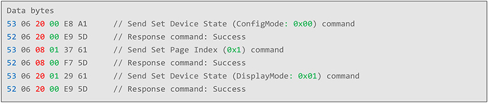
● Set Device State: 0x20
Send Command
| Command Code |
1 Byte |
0x20 |
| Device State |
1 Byte |
0: ConfigMode
1: DisplayMode |
Response command
| Command Code |
1 Byte |
0x20 |
| Error Code |
1 Byte |
0: Success
1: Failed |
Example: Refer to the example of switching pages
■ Explanation and examples of the Event Command protocol
● Page change event: 0x1
Event Command
| Event Code |
1 Byte |
0x01 |
| Parameter data |
2 Byte |
Uint16 PageIndex |
Example: SmartDisplay switches to Page 1.

● Object Text change event: 0x2
Event Command
| Event Code |
1 Byte |
0x02 |
| Parameter data |
N +2 Byte |
Uint16 ObjectId
N byte Unicode Text |
Example: Keypad widget sends the text "1234"

● Object Value change event: 0x3
Event Command
| Event Code |
1 Byte |
0x03 |
| Parameter data |
6 Byte |
Uint16 ObjectId
int32 value |
Example: Object value change event.

Customers can design user interfaces by dragging and dropping widgets in the GUI Builder, providing a WYSIWYG (What You See Is What You Get) design experience that makes UI development more intuitive and efficient. The built-in simulator also allows customers to preview the interface and evaluate the UI design before working with the physical display.
Once the UI is ready, the host controller can communicate with the Smart Display via UART using WINSTAR's proprietary communication protocol, enabling device control and data exchange. This workflow connects UI design, simulation, and device communication, simplifying HMI development and integration.
Before purchasing a UART Smart Display, you can try the GUI Builder and built-in simulator to evaluate the interface design and functionality for your application.
Request GUI Builder Download — simply fill out the online form to receive the download link.