Smart Display supports multiple CAN communication protocols, including CANopen and Custom CAN ID. CANopen is a standardized communication protocol that defines communication profiles, device profiles, and object models for different types of devices, providing a standardized approach to configuring, monitoring, and controlling devices on a CAN bus. On the other hand, when devices on a CAN bus have specific functions or requirements that cannot be addressed by existing standard protocols, Custom CAN ID can be used to define CAN communication according to application requirements, providing greater configuration flexibility.
This article explains how to use an Arduino board, a CAN bus module, and a sensor to switch pages on a 7-inch Smart Display via Custom CAN ID. It covers the hardware components used in the project, Arduino program compilation, and the implementation of page switching on the Smart Display using Custom CAN ID.
Through this demonstration, developers can gain a better understanding of communication and control between the Arduino board, CAN bus module, and Custom CAN ID, and use it as a reference for developing related Smart Display CAN communication applications.
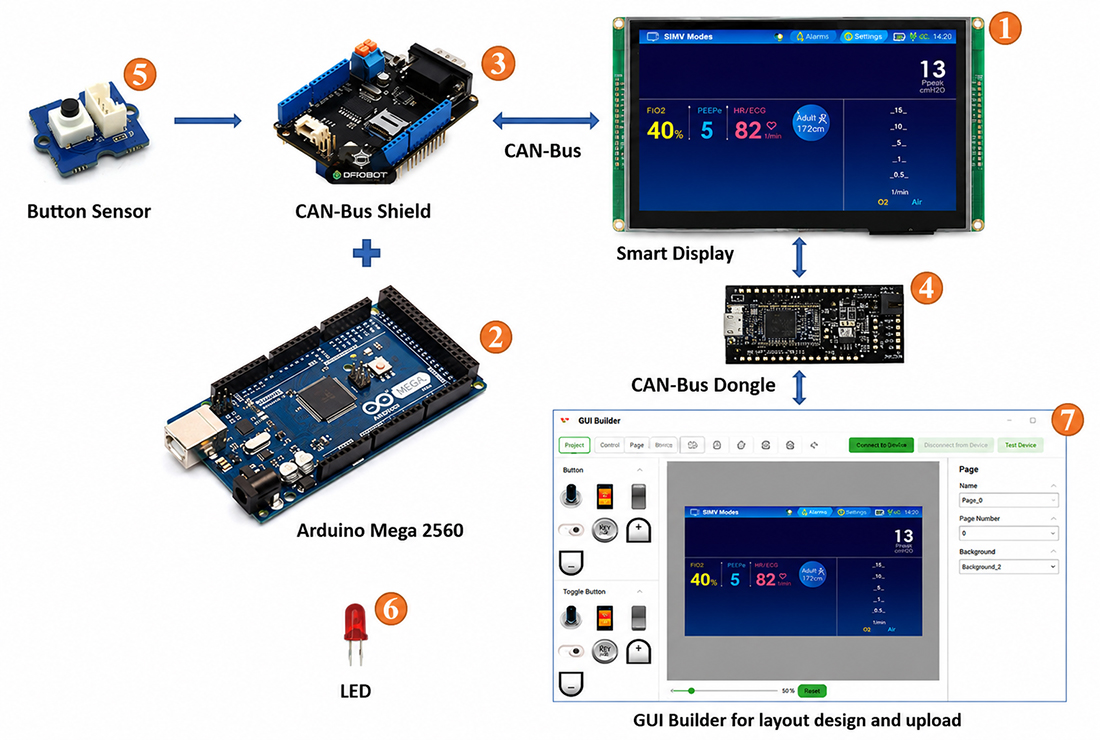
Fig. 1 System Block Diagram
This project uses an Arduino Mega 2560 as the host controller and Arduino IDE v2.0.4 for program development. To communicate with the Smart Display via the CAN bus interface, the Arduino host is connected to a CAN bus shield. The shield uses an MCP2515 CAN controller and an MCP2551 CAN transceiver to enable CAN bus communication between the Arduino host and the Smart Display.
This application requires the following components:
- 7" Smart Display
- Arduino Mega 2560
- CAN bus shield for Arduino Mega 2560
- CAN bus dongle
- Physical Button Sensor
- LED
- Smart Display GUI Builder v0.4.5 or later
This demo is divided into three parts:
- Design the project in GUI Builder.
- Build and upload the project.
- Program the Arduino host.
Design the Project in GUI Builder
To begin, launch the latest version of Smart Display GUI Builder and create a new project. Enter a project name, and the project folder will be selected automatically.
Choose the device type, in this case, a 7-inch device, and select "Custom CAN ID" as the communication protocol. The display orientation is set to landscape mode by default. Next, select a blank UI template and click the "Create" button to create the new project, as shown in Figure 2.
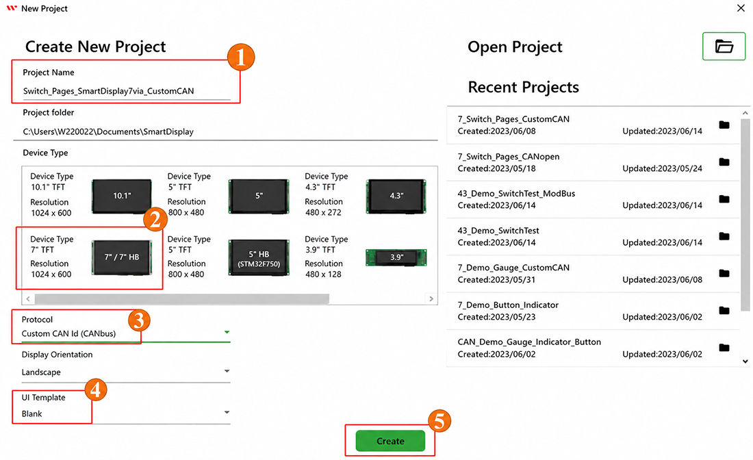
Fig. 2
After the blank project is created, the page shown in Figure 3 will appear.
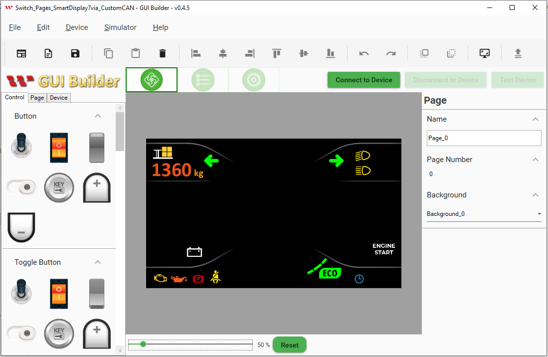
Fig. 3
For this demonstration, a second page is required. Click the "Page" button, and then click the plus button to add a new page.
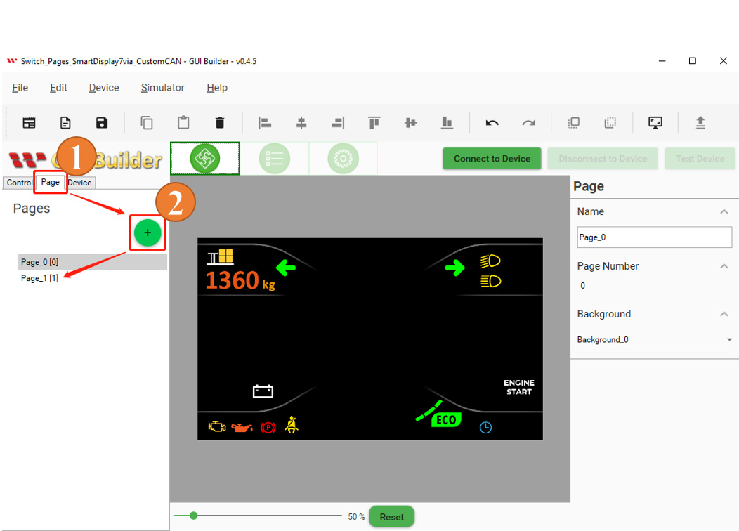
Fig. 4
The background style can be changed from the "Resource" panel.
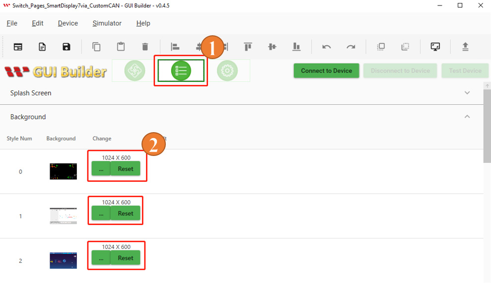
Fig. 5
Select the desired background style from the "background" menu on the right side of the interface.
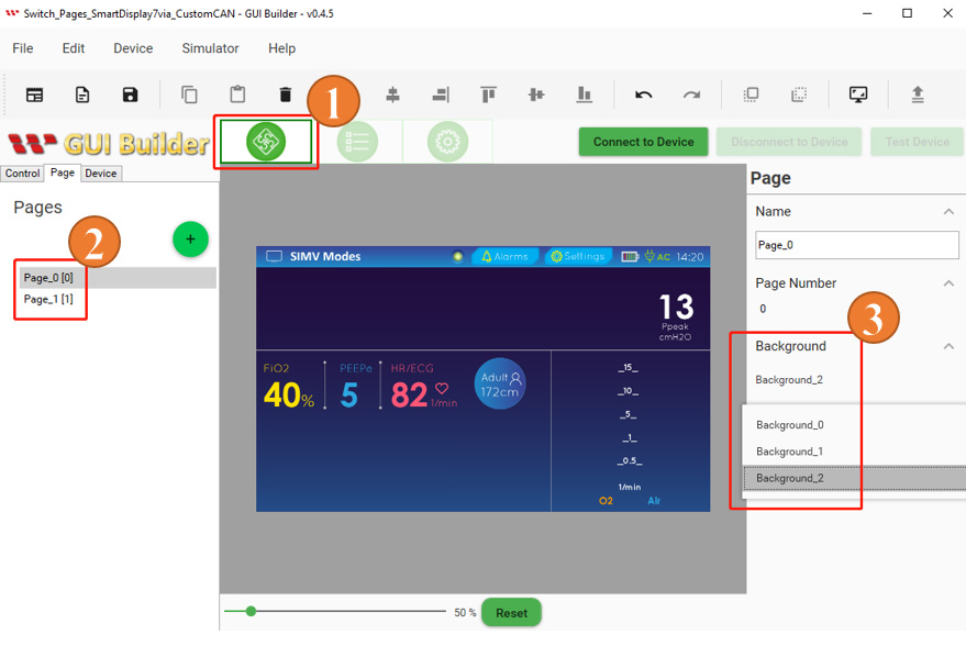
Fig. 6
Build and Upload the Project
After completing the layout design and the previous steps, the project is ready to be built and uploaded. Click the "Device" button and select "Device Property". Review the protocol and baud rate settings and adjust them as needed. Make sure the baud rate in GUI Builder matches the baud rate configured in the Arduino program. After completing the settings, click "Connect to Device". Once the device is connected successfully, click "Upload" to upload the project, as shown in Figure 7.
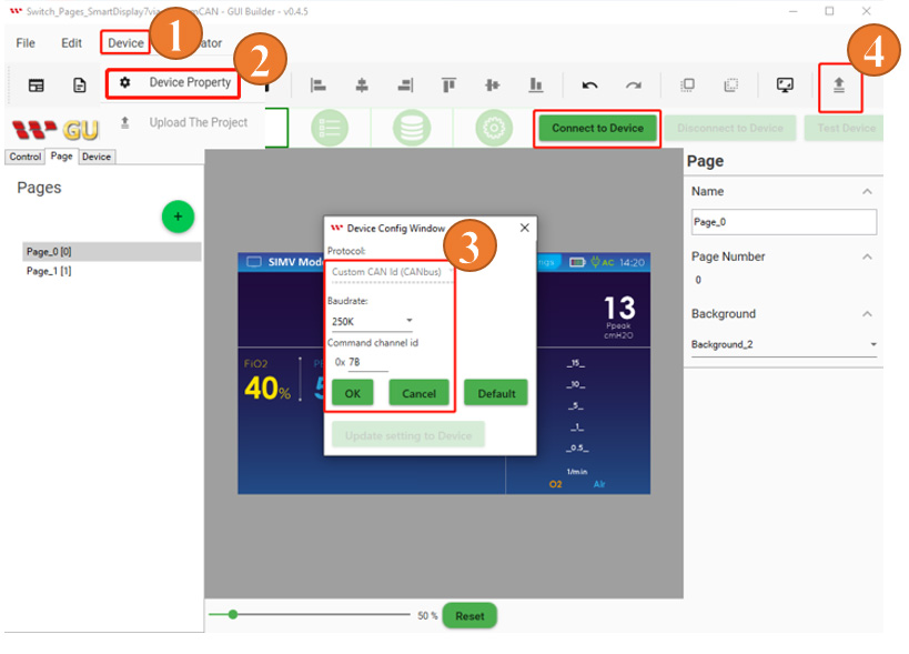
Fig. 7
When the project upload is complete, click "OK", as shown in Figure 8.
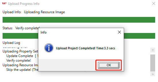
Fig. 8
After the upload is complete, the startup screen will appear on the Smart Display, as shown in Figure 9.
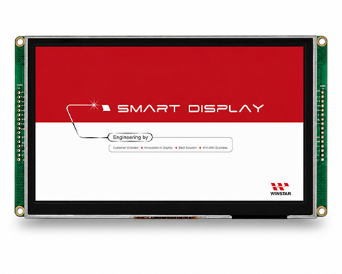
Fig. 9
The display then switches from the startup screen to the project page, indicating that the project has been successfully built and uploaded through GUI Builder, as shown in Figure 10.
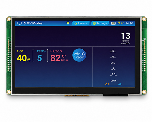
Fig. 10
Program the Arduino Host
The mcp2515_can.h library is used for Custom CAN ID communication, while the SPI.h library is used for Serial Peripheral Interface (SPI) communication. The mcp2515_can.h library provides communication with the MCP2515 CAN (Controller Area Network) controller, which is commonly used in embedded systems.
The library provides functions for initializing the MCP2515, configuring CAN communication parameters such as the bit rate, filters, and masks, transmitting and receiving CAN messages, and checking for errors. In the Arduino IDE program, the settings required for CAN communication are defined in the code shown in Figure 11, including the CAN ID, control parameters, and related variables. This code segment initializes the global variables, constants, and arrays required later in the program, along with their respective data types.
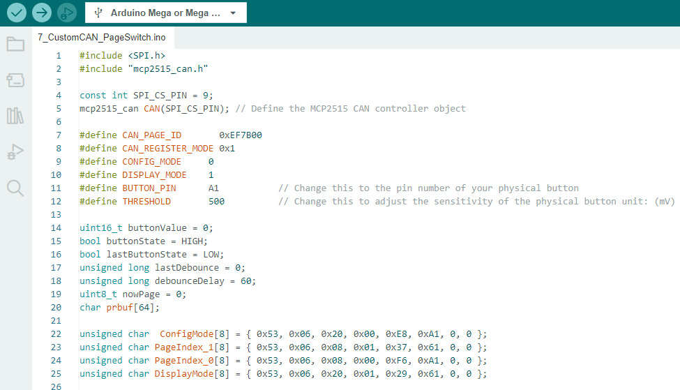
Fig. 11
This code segment contains the setup() function, which runs once when the program starts. Serial.begin() initializes serial communication with the Serial Monitor at a baud rate of 115200. The built-in LED pin is configured as an output using pinMode(), while the physical button pin is configured as an input. A while loop is then used to initialize the MCP2515 CAN controller, and CAN.begin() is called with CAN_250KBPS to set the CAN bit rate to 250 kbps.
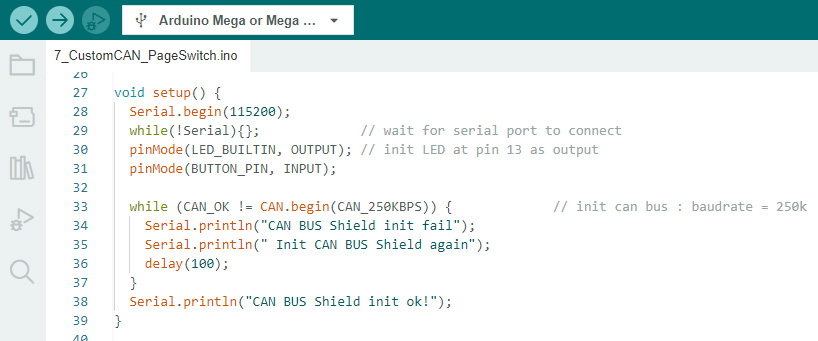
Fig. 12
The changePageFunction() function sends CAN commands through the MCP2515 to switch pages on the Smart Display using CAN messages with specific data bytes. The function first sends a "device mode" command to put the Smart Display into configuration mode, followed by a "change page" command with the desired page number. Finally, it sends another "device mode" command to return the Smart Display to display mode.
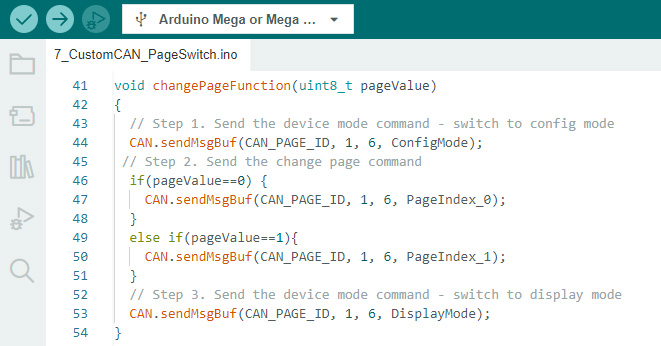
Fig. 13
This code segment contains the loop() function, which runs repeatedly after the setup() function has completed.
The program reads the voltage value of the physical button using analogRead() and stores it in the buttonValue variable. If buttonValue is greater than the THRESHOLD value, this indicates that the physical button has been pressed. The program then increments the nowPage variable by 1 and outputs the current nowPage value to the Serial Monitor using sprintf() and Serial.println().
Next, the program passes the current nowPage value to changePageFunction() to switch to the specified display page. If nowPage is not 0, digitalWrite() turns on the built-in LED on pin 13; otherwise, the LED is turned off. The lastDebounce variable is updated with the current time using millis() to record the time of the most recent button press. The program continuously reads buttonValue within a while loop until the physical button is released.
Finally, delay(100) introduces a 100 ms delay at the end of the loop so that CAN bus messages are transmitted at an appropriate interval.
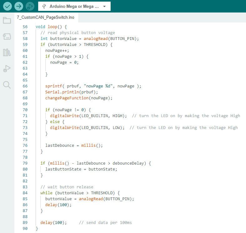
Fig. 14
For more details, refer to the Arduino code. When establishing communication between the host and the Smart Display, make sure the relevant CAN communication settings are configured correctly. For more information about communication between the host and the Smart Display, refer to the communication log in GUI Builder.
After successfully verifying and uploading the program in Arduino IDE, the display pages can be switched using the physical button. When the Smart Display shows the first page, the LED remains off. Pressing the physical button switches the display to the second page and turns on the LED, as shown in Figure 15.
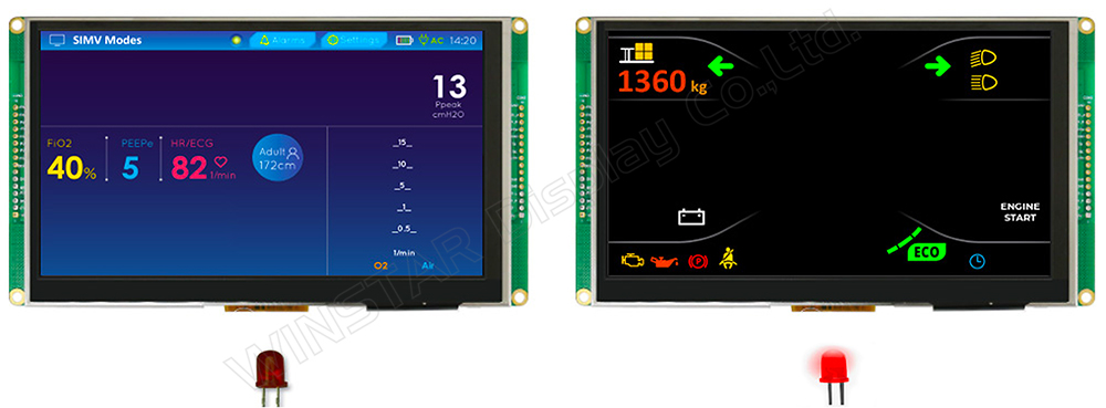
Fig. 15
This completes the demonstration of switching Smart Display pages via Custom CAN ID.
To download the program, demo video, and related resources, refer to the GitHub project page. The actual hardware setup is shown in Figure 16.
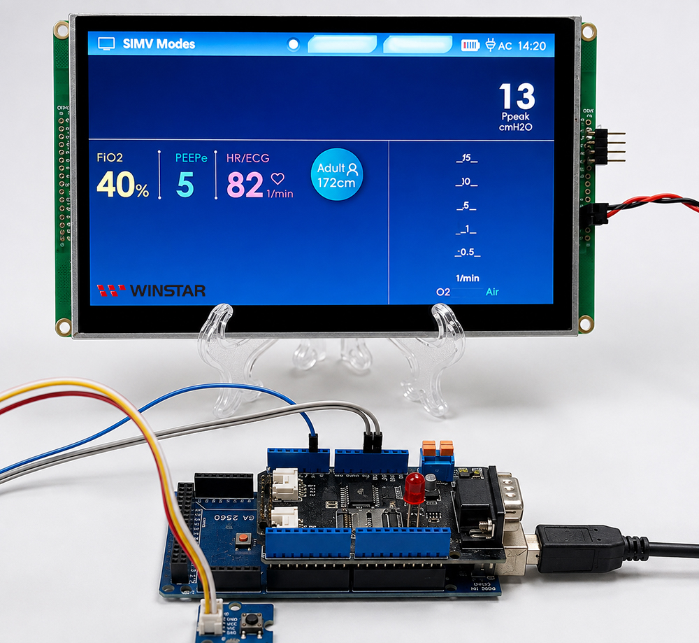
Fig. 16
Conclusion
This example demonstrates how to use an Arduino board with an MCP2515 CAN controller to switch pages on a Smart Display via Custom CAN ID. The Arduino host reads the input from a physical button and sends CAN commands through the MCP2515 to the Smart Display to switch between display pages.
Through this example, developers can gain a basic understanding of Custom CAN ID communication and control between an Arduino host and a Smart Display, providing a reference for developing other Smart Display CAN communication applications.