Modbus Communication between Host and Smart Display
To help developers get started with WINSTAR Smart Display and make its operation easier to understand, we continue to provide practical demo projects covering different application scenarios. In this article, we present another Modbus demo to help both beginners and experienced developers quickly understand the fundamentals.
Modbus is widely used in industrial automation to communicate with and control various devices and sensors. In this application, an Arduino board serves as the host controller for system integration. Using Modbus, the Arduino can work with various sensors and toggle buttons to control the Smart Display, Gauge, Indicator, and LEDs. This demo uses an Arduino Mega 2560 with an RS485 shield to communicate with a Smart Display via Modbus.
The program demonstrates how to read sensor values, switch display pages, and control LEDs based on sensor readings using Modbus registers.
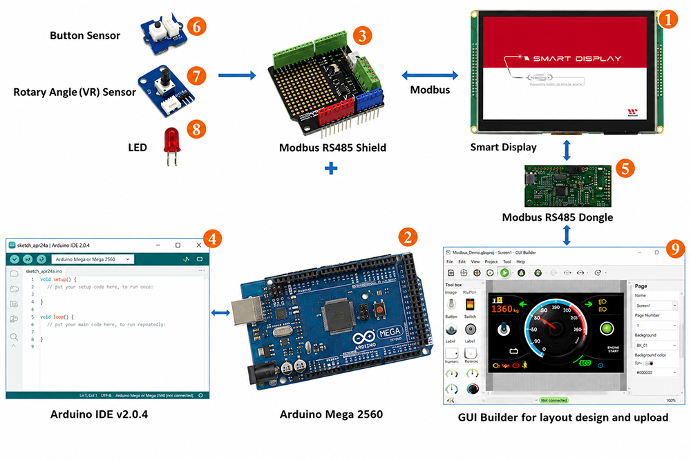
System Block Diagram
The following components are required for this application:
- 7-inch Smart Display with Modbus
- Arduino Mega 2560
- RS485 Modbus Shield for Arduino Mega 2560
- Arduino IDE v2.0.4
- Modbus RS485 Dongle
- Physical Button
- Variable Resistor (Rotary Angle) Sensor
- LED
- GUI Builder v0.4.2 or later
The demo is divided into three parts:
- Design the demo project in GUI Builder.
- Build and upload the project.
- Program the Arduino host.
Design the Demo Project in GUI Builder
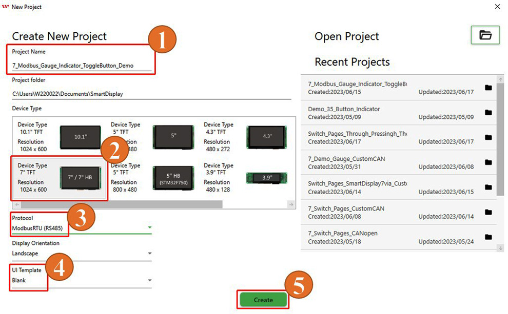
First of all, open an updated GUI builder to create a new project, and then type the project name, then check the project folder which is auto-selected by default. And then select the device type, which I have selected 7 ". Then select the protocol, then let the display orientation be by default landscape mode. And then select blank in the UI Template and finally click on the create button to create your new project, as shown in Fig.
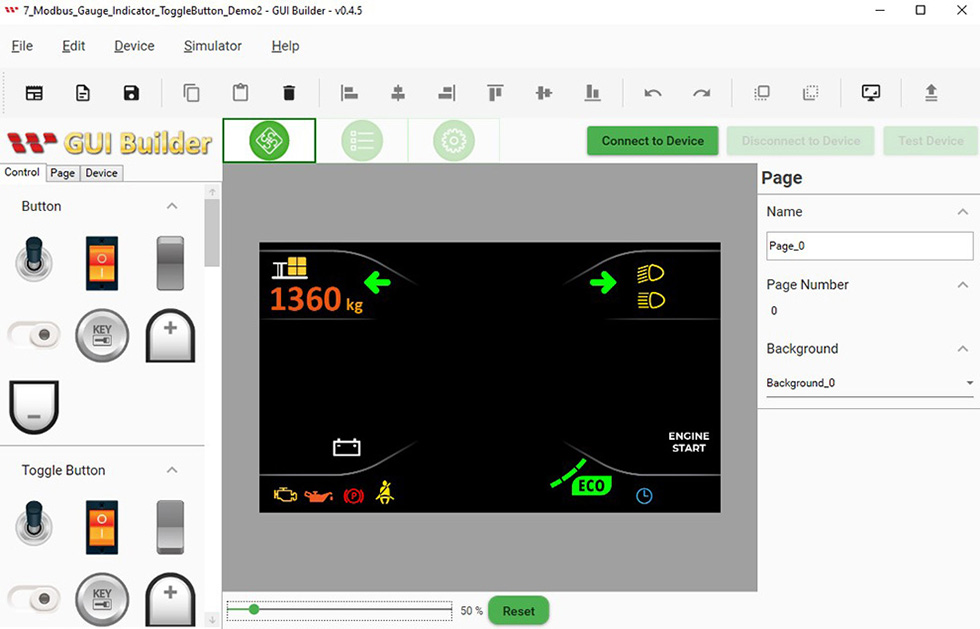
This page opens after creating the project.
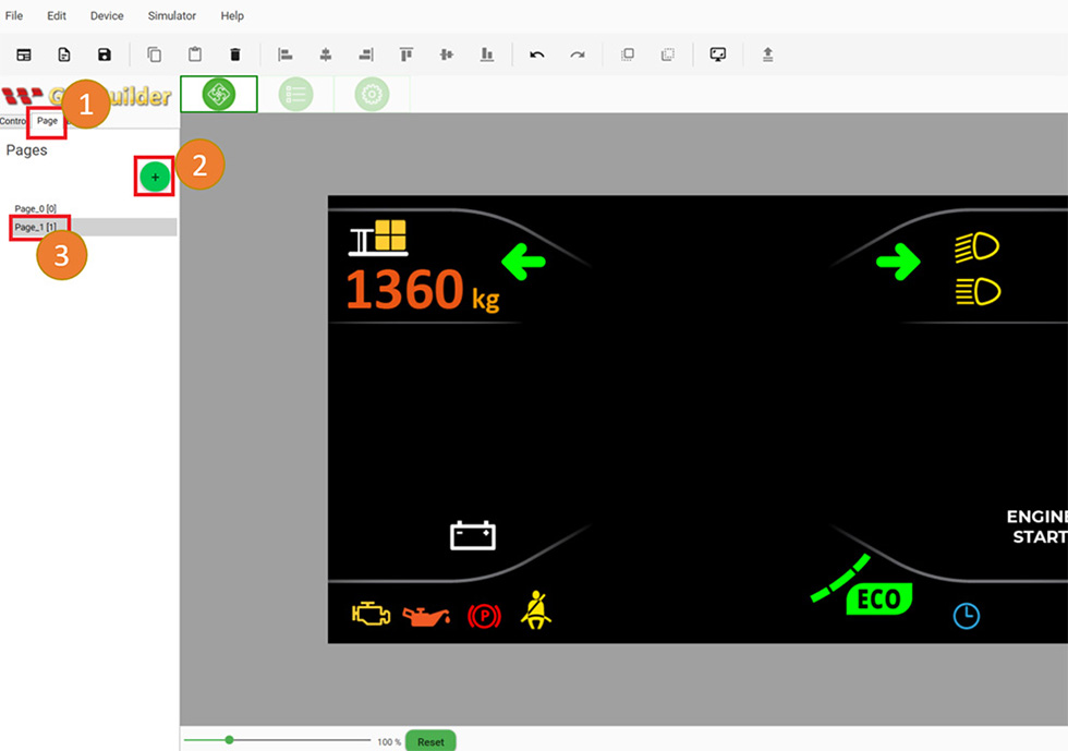
As per the demo scenario, one more page needs to be added. For this, click on the page button and then click on the plus button.
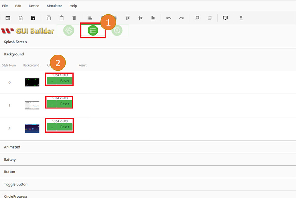
Background style could be chosen the customized background in the resource panel.
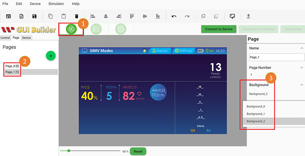
The background style could be selected in the page section also.
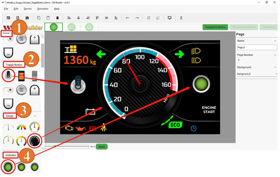
Now go back to the Controls section on the first page. According to the demo scenario, select the toggle button, and drag and drop it into the page layout area. Do the same thing for the gauges and indicators also.
Build and Upload the Project
After completing all the previous steps by creating two separate pages and placing toggle buttons, gauges, and indicator widgets on the first page, it is time to build the project. Go to the Page Info section. Click on the Device button and choose Device Properties. Check Protocol, then select the COM port and set the baud rate. Then connect the device by clicking the "Connect to device" button. And finally, click on the Upload button to upload the project, as shown in the figure below. Wait for project uploading to complete.
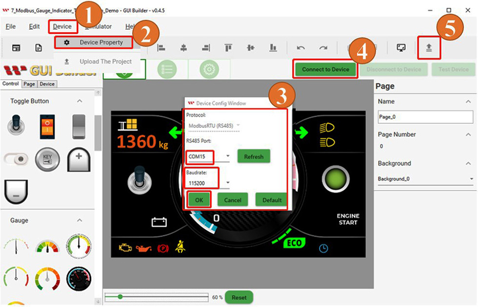
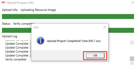
When the Upload project is completed then click on the ok button as shown below Fig:
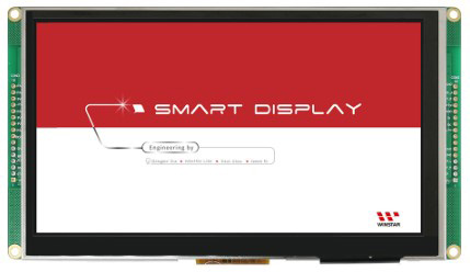
The start screen will appear after uploading is completed as shown below Fig:
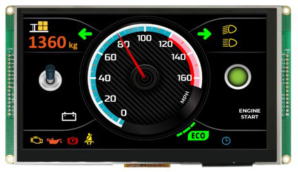
After the start screen, it will switch to the first page. Now Building and uploading has completed through GUI builder as shown below Fig:
Program the Arduino Host
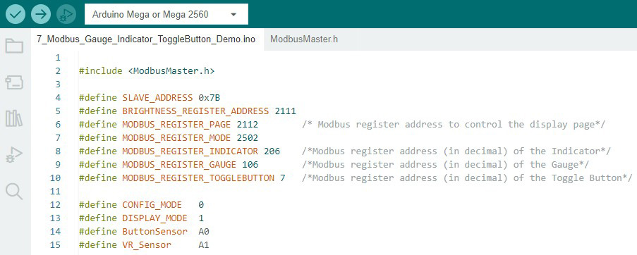
Here all required register address and define in the Arduino IDE program as shown in below Fig: The program starts by defining the pins of the physical button sensor, variable resistor sensor, and LEDs. It then initializes the Modbus communication using the ModbusMaster library. The program sets the Modbus register addresses for controlling the display page, the Indicator, the Gauge, and the Toggle Button.
If you want to learn more about this communication process, you should refer to the Test Device or Simulator section of the GUI builder communication log to see how the communication between the host device and the smart display takes place using a communication protocol called Modbus RS485.
Here log message data of the “Toggle button” is shown in the image below. This log message data is telling, how to access the data for the toggle button on the smart display. The second byte of the Data Byte is the 00 06 hexadecimal value. Which represents the address of the toggle button, after converting this value to a decimal value, it will be 6. Which can be used to write or insert data into the button. However, in this case, the toggle button is used as a function to read or retrieve data from the Smart display. Here we use the registered address "7" to read the data from the toggle button.
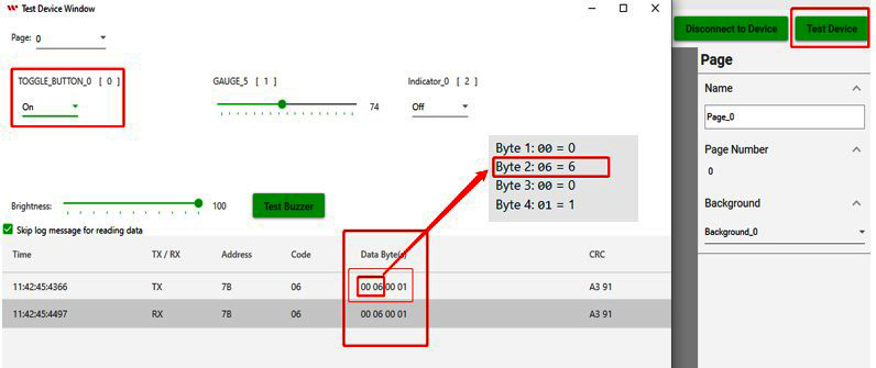
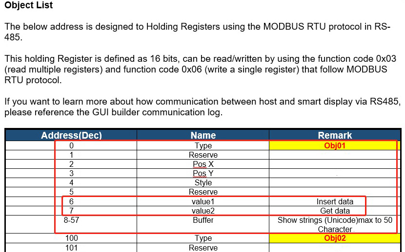
And now the question arises why do we use this registered address "7" to receive data from the toggle button? It would be highly recommended to consult the datasheet for the Modbus Smart Display to get more detailed information on this communication process. The screenshot of the data sheet is shown in the image below, which shows the address used by the 1st object (widget) Toggle Button.
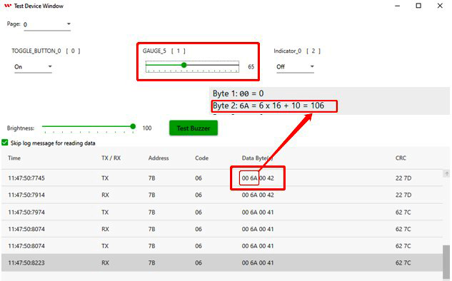
Here log message data of the “Gauge” is shown in the image below. This log message data is telling, how to access the address of the Gauge. The second byte of the Data Byte is the 00 6A hexadecimal value. Which represents the address of the Gauge, after converting this value to a decimal value, it will be 106. Which can be used to write or insert data into the Gauge widget.
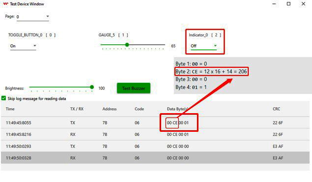
Here log message data of the “Indicator” is shown in the image below. This log message data is telling, how to access the address of the Indicator. The second byte of the Data Byte is the 00 CE hexadecimal value. Which represents the address of the Gauge, after converting this value to a decimal value, it will be 206. Which can be used to write or insert data into the Indicator widget.
ADC_REF: constant is set to a value of 5V and represents the reference voltage of the ADC (analog-to-digital converter) and is used to adjust the sensitivity of a physical button unit. GROVE_VCC: constant is set to a value of 5 and represents the VCC voltage of the Grove interface used in the circuit. FULL_ANGLE: constant is set to a value of 300 and represents the full value of the rotary angle used in the circuit. The comment suggests that this value is measured in degrees.

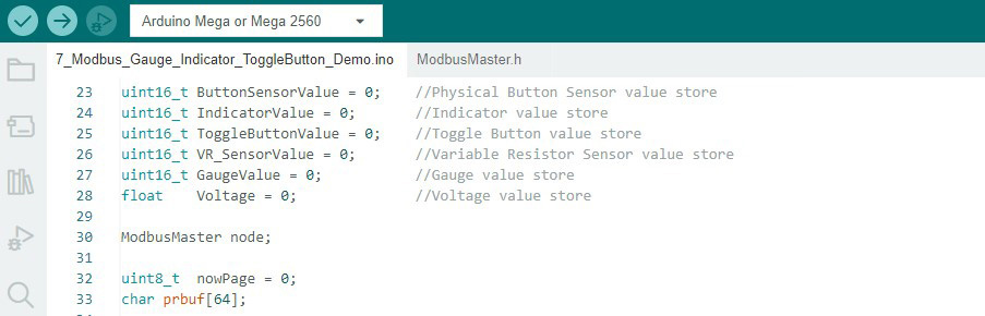
Here a number of necessary variables are set and data types declared, and initialized to zero.
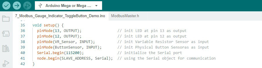
Define all pin mode and setup for external accessories like physical button and LED. Also setup the baud rate for serial communication as shown in below Fig:
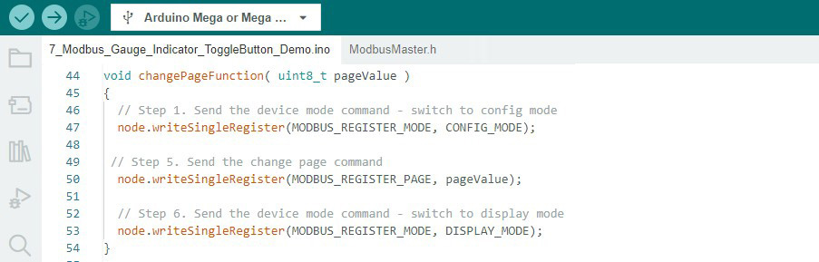
The following figure shows that the "ChangePageFunction" has been defined. And "writeSingleRegister" function is used to write the data.
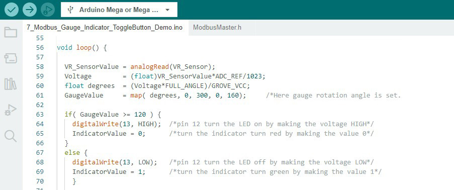
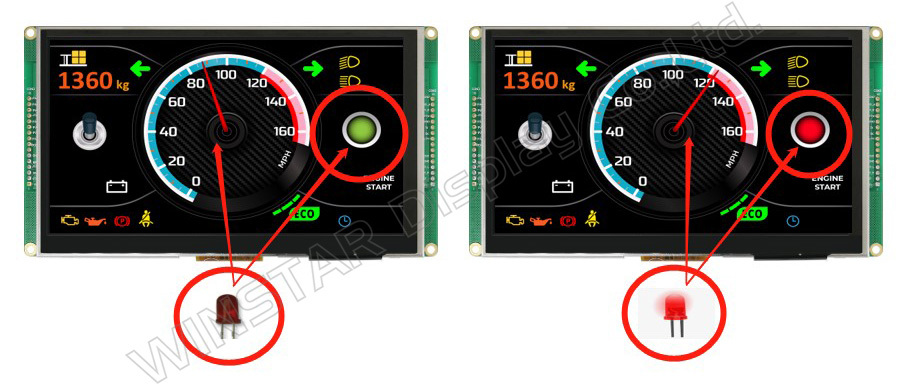
The following figure shows that when the Arduino host reads the value change of the Variable Resistor (Rotary Angle) Sensor, it will send the value to the Smart Display through the Modbus communication protocol to change the Gauge value. When the gauge value is less than 120, the LED on pin 13 is in OFF mode and the indicator is green. And when the gauge value is equal to or greater than 120 then the LED turns on and the color of the indicator turns red.
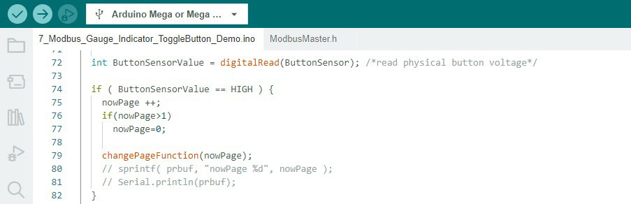
The following figure shows that when the Arduino host reads the value change of the physical button sensor, it will send the value to the Smart Display through the Modbus communication protocol to change the page.
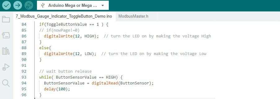
The following image shows that the Arduino host reads the toggle button's value change by receiving the value from the smart display through the Modbus communication protocol to turn on the LED on pin 12.
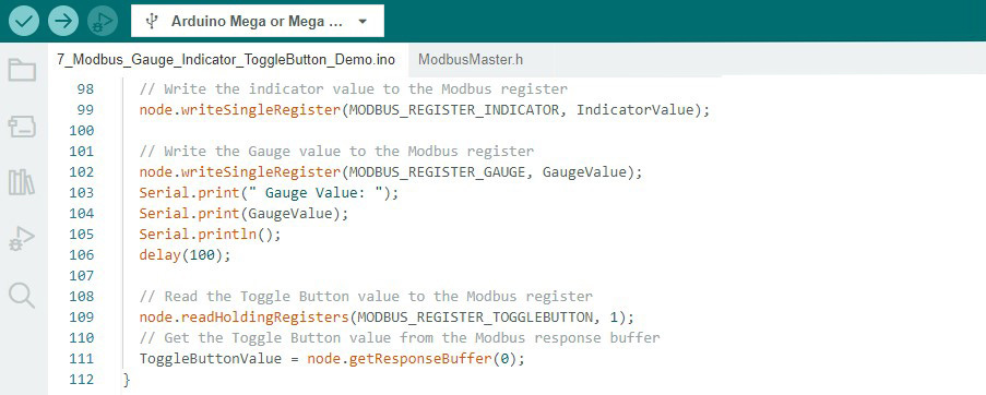
This is a very important section, here we have used the "writeSingleRegister" function to write or insert data, for communication with a smart display and the "readHoldingRegisters" function to read or receive data from the smart display. It is very important to pay attention to the delay function here to communicate with active widgets like a gauge. In Modbus protocol, once we send data and then get acknowledgment then we can send data again. Therefore, it becomes necessary to use a delay function between transmitting and receiving data through the Modbus protocol.
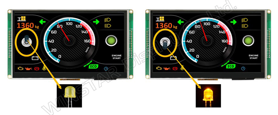
After successfully verifying and uploading this program through Arduino IDE. It would be possible to perform the demo scenarios. When the toggle button is in the off state, the external attached LED on pin 12 is also in the off position. And when the toggle button is in ON mode the external attached LED turns on immediately as shown in the picture below:
The gauge is controlled by a variable register sensor as per the demo scenario. When the gauge value is between 0 and 120, the indicator is shown in green, and the LED on pin 13 is off. But when the gauge value exceeds 120 value, the indicator turns red and the LED at pin 13 turns on as shown in the picture below:
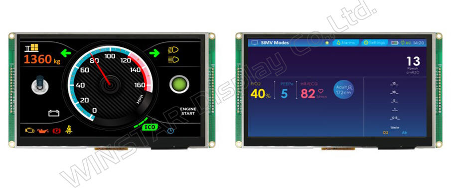
In this demo scenario, it is possible to switch between pages by pressing the physical button. When the physical button sensor is pressed, the display switches to the second page, and when it is pressed again, it switches back to the first page, as shown in the picture below.
Congratulations, the design demo is completed in Smart Display 7" with various sensors and LED to change the display while pressing the physical button and control the Gauge, Indicators and external LED. Please refer to this link of GitHub (https://bit.ly/3oT0o5M) to download the above program and can seek more details about this demo project.
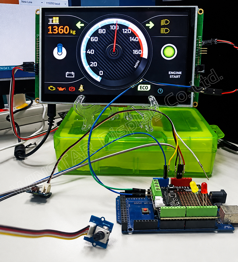
Note: Please follow this link for more details about Modbus RS485 shield which used in this demo project (https://media.digikey.com/pdf/Data%20Sheets/DFRobot%20PDFs/DFR0259_Web.pdf ). The actual hardware setup fig is given below.
Conclusion
Overall, the program serves as an example of how to use an Arduino board and Modbus protocol to control sensors and indicators. It showcases how to read sensor values, change display pages, and control LEDs based on sensor readings using Modbus registers. The program can be beneficial for both beginners and experienced developers looking to learn more about the Modbus protocol and its applications in controlling smart displays.