CANopen Communication Between the Host and Smart Display
Controlling a Smart Display requires a system interface and communication protocol. From a host-control perspective, this article uses a practical Arduino example to demonstrate how the HOST sends commands to change the color of an indicator on the Smart Display. In this example, a touch button is placed on the UI and a physical button is connected to the Arduino. Pressing either the physical button or the touch button changes the color of the on-screen indicator and turns the external LED on or off.
This application demonstrates how to use an Arduino development board to control a 3.5-inch CAN Smart Display, including how to program the physical button, touch button, on-screen indicator, and LED on the board, as well as how the Smart Display receives commands from the HOST. An Arduino Mega 2560 equipped with a CAN Bus shield serves as the host controller and communicates with the Smart Display via CANopen.
The system block diagram is shown below:
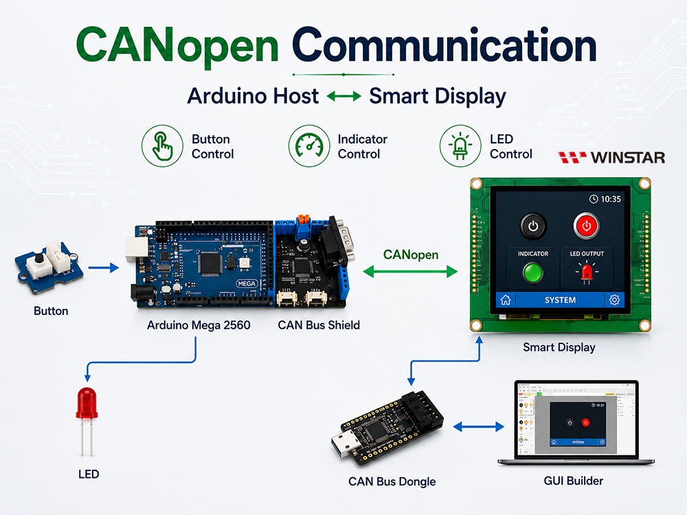
System Block Diagram
The following components are required for this application:
- 3.5-inch CANopen Smart Display
- Arduino Mega 2560
- CAN Bus shield for Arduino Mega 2560
- CAN Bus Dongle
- Physical button
- LED
- Smart Display GUI Builder v0.4.2 or later
This demo is divided into three parts:
- Design the project in GUI Builder
- Build and upload the project
- Program the Arduino host
Design the Project in GUI Builder
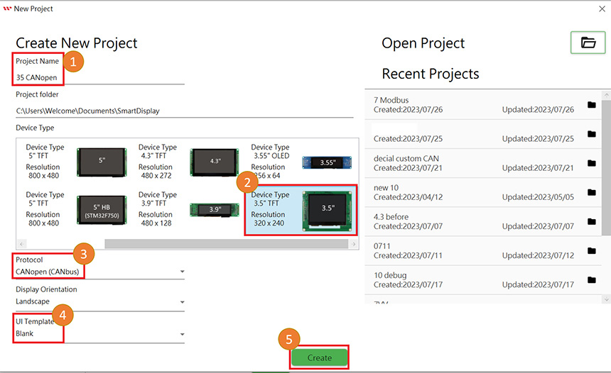
First, create a new project and enter a project name. Select the device type; this example uses a 3.5-inch device. Select CANopen as the communication protocol and set the display orientation to Landscape. Next, select the Blank Template from the UI templates, and then click Create to create the new project, as shown below.
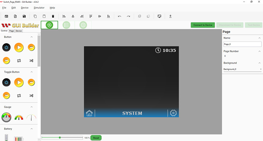
After completing these settings, a blank page will open.
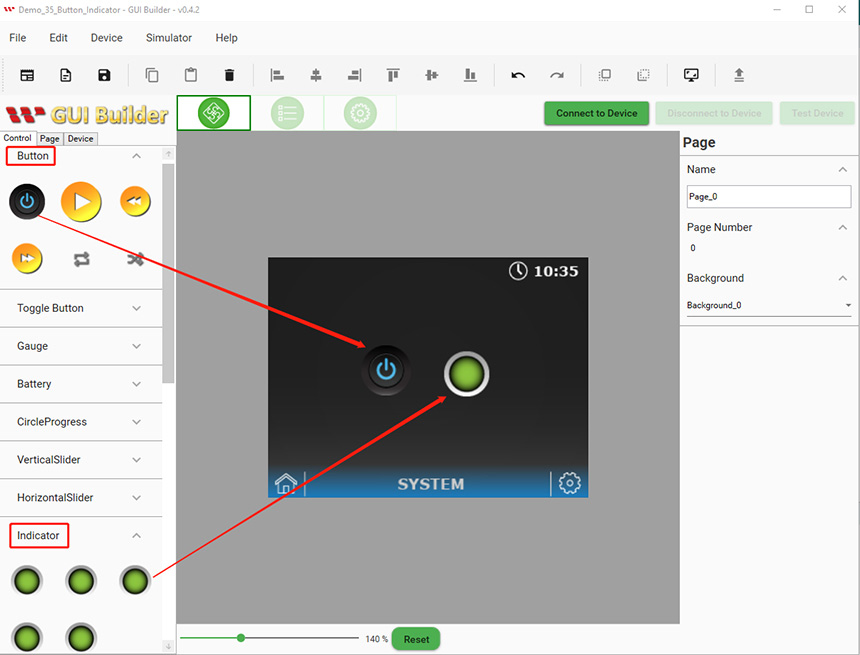
For this application example, add a touch button and an Indicator widget to the workspace. Select the required widgets from the control panel and drag them onto the workspace, as shown below.
Build and Upload the Project
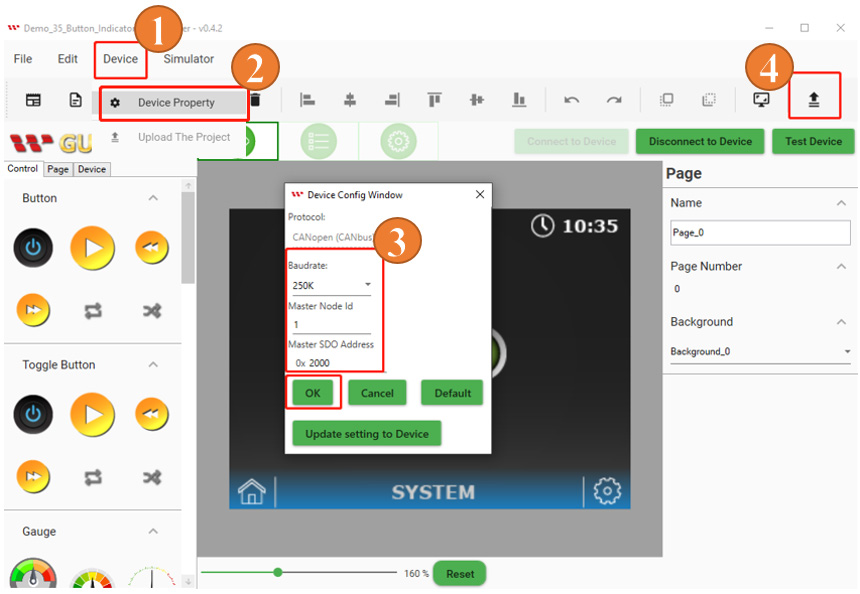
After completing the previous settings and UI design, the project is ready to be built and uploaded. Click Device on the GUI Builder toolbar and select Device Property. In the Device Property window, you can use the default baud rate or adjust it according to your application requirements. Make sure that the baud rate configured in the Arduino program matches the setting in GUI Builder. After completing the settings, click Upload to upload the project to the Smart Display, as shown below.
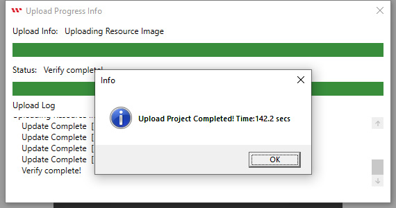
When the project upload is complete, the message "Upload project completed" will appear. Click OK to close the window, as shown below.
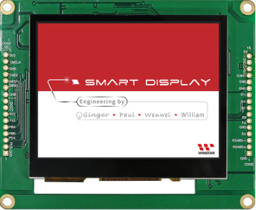
After the upload is complete, the Smart Display will show the startup screen, as shown below.
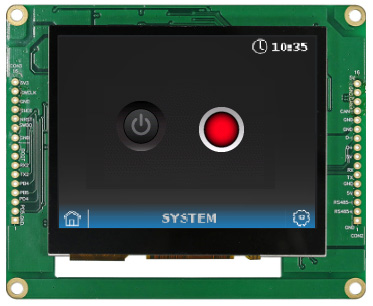
After the startup screen, the Smart Display will switch to the uploaded application page, indicating that the project has been successfully built and uploaded.
Program the Arduino Host
This example uses Arduino IDE v2.0.4 to program the Arduino host. The mcp2515_can.h library and several supporting libraries are used for CAN Bus communication. For more details, refer to the Arduino code. When establishing communication between the host and the Smart Display, it is important to verify the addresses associated with the objects. For more information about CAN Bus communication between the host and the Smart Display, refer to the communication log in GUI Builder. The required object addresses are defined in the Arduino IDE program, as shown below.
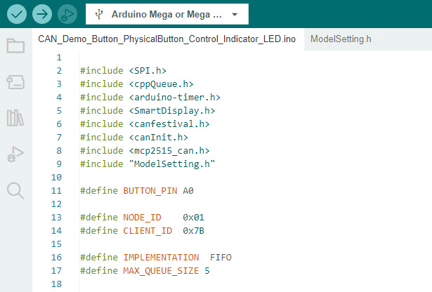
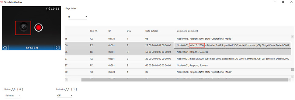
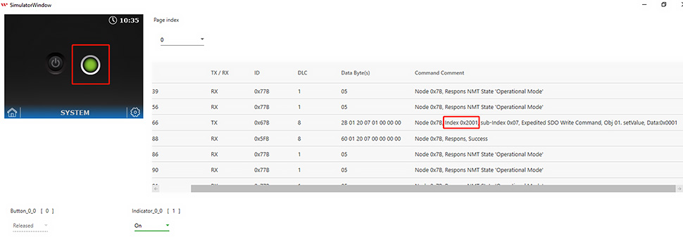
In the CANopen structure, the index of the Button style corresponds to 0 (0x2000), while the index of the Indicator style corresponds to 1 (0x2001). It is important to take note of each object's index. If the index of an object is known, its status can be changed through the Arduino host program. The corresponding object indexes can be observed in the command information shown in the simulation log table below:
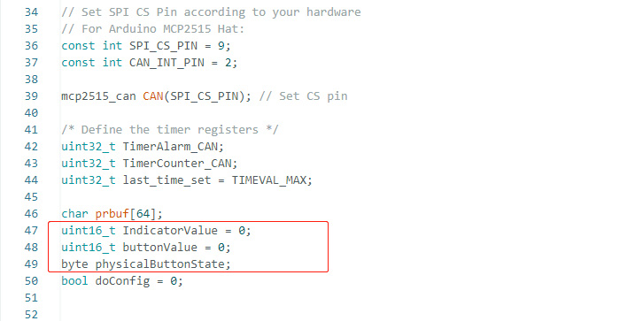
The data type of each object is defined here. If additional objects are required, their corresponding data types must also be defined in the program.
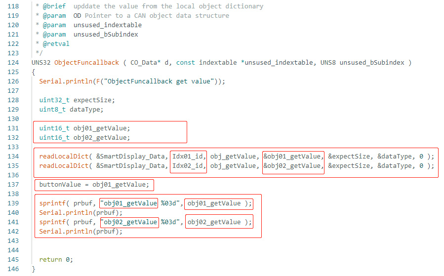
The following figure shows how ObjectFunCallback handles the values received from each object. Users can modify the code or add additional object-handling logic according to their application requirements.
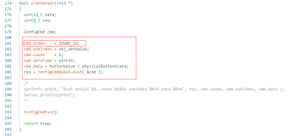
When the Arduino host detects a change in the physical button state, it sends the corresponding value to the Smart Display via CANopen. Refer to the following code for the IDs and sub-indexes used in the command structure. This section of the program updates the value of the Indicator (object index 2) according to the state of the physical button.
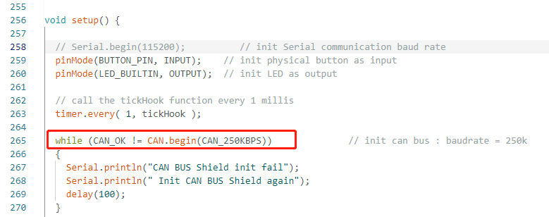
Define the register addresses for all objects, configure the pin modes for external components such as the physical button and LED as inputs or outputs, and set the baud rate, as shown below:

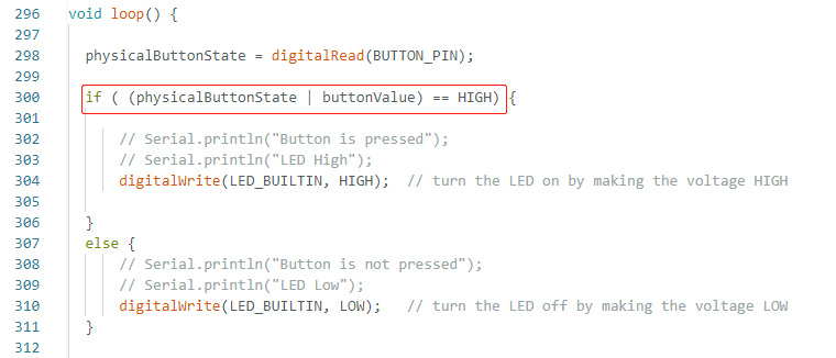
Finally, the logic required for this application scenario is defined in the loop(). When either the physical button or the touch button on the Smart Display is pressed, the system changes the color of the on-screen Indicator and turns the external LED on or off.
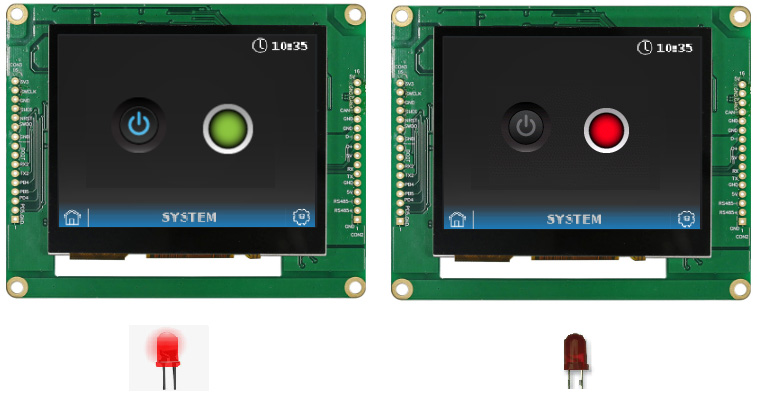
After successfully verifying and uploading the program through Arduino IDE, pressing either the physical button or the touch button on the Smart Display turns on the LED and changes the Indicator color to green. When the Indicator is red and the LED is off, neither the physical button nor the touch button is being pressed, as shown below.
The program described above can be downloaded from the GitHub link. Additional files and information about this demo project are also available in the examples. The actual hardware setup is shown below.
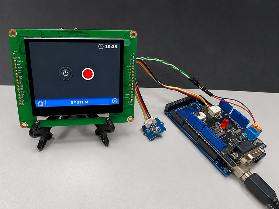
After completing these steps, the physical button or the touch button on the Smart Display can be used to control the on-screen Indicator status and the external LED, completing this Smart Display CANopen communication demo.
Conclusion
This example demonstrates the operation and application of GUI Builder while helping users understand how to develop host-side control applications using CAN Bus. It also shows how the host sends and receives commands to control the Smart Display. Through this example, developers can gain a better understanding of CANopen communication and control between the host and the Smart Display and use it as a reference for developing Smart Display applications.