Smart Display currently supports the CAN bus hardware communication interface and uses the CANopen communication protocol. CANopen is a widely used industrial communication protocol based on the CAN bus and is used in various fields, such as medical equipment, vehicles, railway applications, and building automation. However, when using the CANopen protocol, the client needs to implement the corresponding CANopen communication mechanism on the host side. This may add complexity for applications that simply require CAN bus communication. Therefore, to simplify implementation, we developed the Custom CAN ID protocol, which does not require the client to implement the CANopen protocol. Instead, data can be configured through a custom DBC file to associate CAN IDs and data with widgets on the Smart Display, enabling real-time interaction. This approach helps customers better understand and control system data while providing greater flexibility and easier maintenance.
The Custom CAN ID protocol mainly uses a DBC (CAN Database) file to configure data and define how CAN data interacts with widgets on the Smart Display. The DBC file defines relevant information such as CAN IDs, message formats, and decoding information. By using a custom DBC file, different CAN IDs and data can be associated with widgets on the Smart Display, enabling real-time interaction. For example, CAN IDs and data can be used to control graphics or text on the display, while buttons or sliders on the display can be used to control CAN data. This interaction helps customers better understand and control system data, resulting in a flexible and maintenance-friendly solution.
Understanding DBC Files
A DBC file is typically an ASCII plain-text file that contains information about the physical signals transmitted on the CAN bus, including the CAN ID, signal name, scaling factor, and definition. The file is used to decode raw CAN data into meaningful values and map different CAN IDs to their corresponding signals. A DBC file provides the information needed to convert CAN message payloads into physical signal values.
Raw CAN Data Decoding Example

If you have a CAN DBC file that includes the decoding rules for CAN ID 0x181, the information in the DBC file can be used to decode the following data.

One of the main functions of a DBC file is to describe the rules for decoding CAN messages and signals. The following example shows test data excerpted from a DBC file:

Based on the DBC information above, the following decoding information can be obtained:
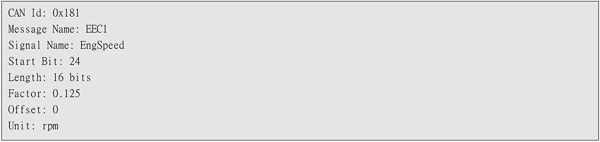
Using the decoding rules above, the previously obtained Raw CAN Data can be decoded into the following information:
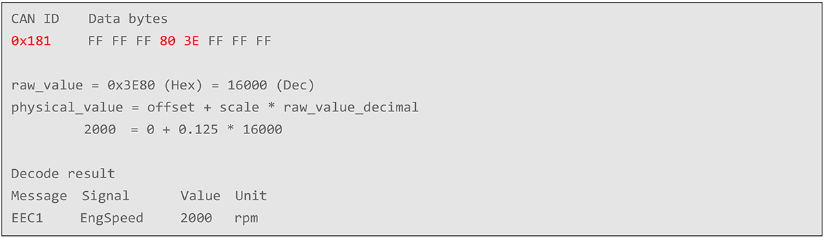
As shown in the example above, the settings defined in a DBC file can be used to correctly decode the actual values represented by the CAN data associated with a CAN ID. A DBC file contains the layout and definitions of CAN messages and signals, allowing raw CAN data to be interpreted and converted into corresponding physical values so that the system can understand the information transmitted over CAN.
DBC Editor
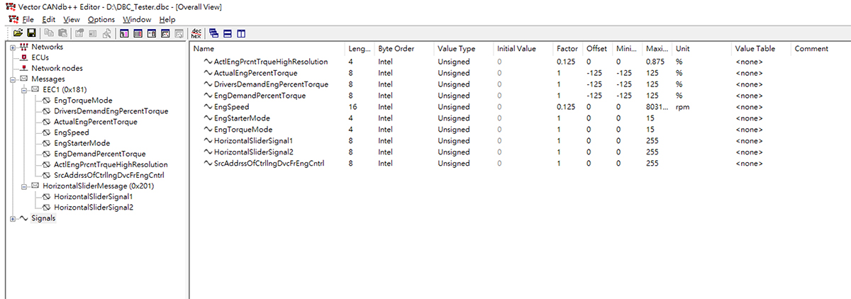
Because the structure and format of a DBC file can be difficult to read and edit directly, DBC editor tools can be used to help create and edit custom DBC files. One commonly used DBC editor is Vector CANdb++, developed by Vector Informatik GmbH. It provides a graphical interface for creating and editing DBC files, adding messages and signals, and defining related attributes such as message IDs, start bits, lengths, scaling factors, and offsets.
Smart Display GUI Builder – Custom CAN ID Configuration
Smart Display GUI Builder provides an intuitive interface for creating Custom CAN ID projects. Simply import a DBC file and associate the messages/signals with the corresponding widgets to enable data display and interaction on the Smart Display. The following sections explain how to create a Custom CAN ID project in Smart Display GUI Builder and configure the relationships between the DBC file and widgets.
Create a Custom CAN ID Project
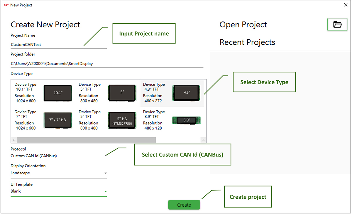
Enter the Project name, select the Smart Display device type, and select "Custom CAN Id (CANbus)" under Protocol to create a Custom CAN ID project.
Import a Custom DBC File
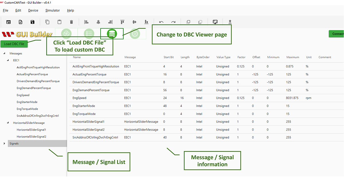
Switch to the DBC Viewer page and click "Load DBC File" to import a custom DBC file. After importing the file, you can view the Messages, Signals, and related configuration information defined in the DBC file.
Configure the Gauge and Horizontal Slider Widgets
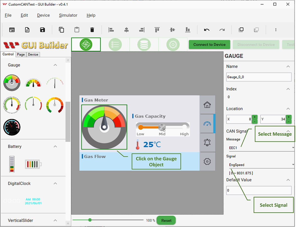
Select the Gauge object and, in the CAN Signal section of the Gauge properties, set Message to EEC1 and Signal to EngSpeed. This associates the Gauge with EngSpeed. Once configured, the value displayed by the Gauge changes according to the EngSpeed value.
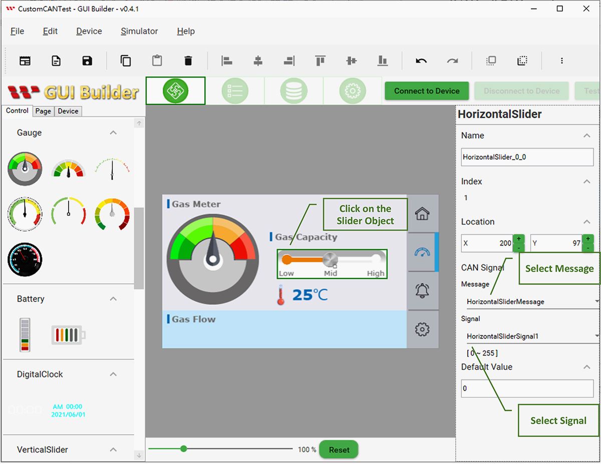
Select the Horizontal Slider object and, in the CAN Signal section of the Horizontal Slider properties, set Message to HorizontalSliderMessage and Signal to HorizontalSliderSignal1. This associates the Horizontal Slider with HorizontalSliderSignal1. Once configured, the Horizontal Slider changes according to the HorizontalSliderSignal1 value.
Simulate CAN ID / CAN Data and Widget Interaction
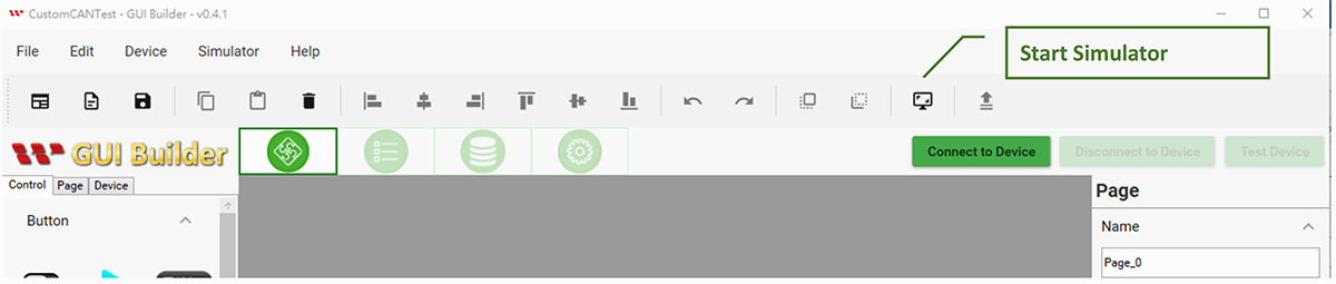
Click the "Simulator With GUI" icon to start the simulator.
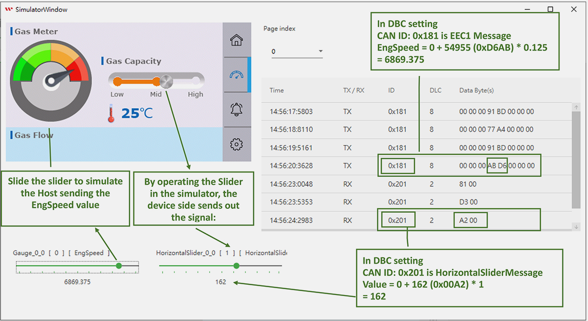
After starting the simulator, move the EngSpeed slider at the bottom to simulate the Host sending EngSpeed data and observe the corresponding changes in the Gauge in the simulator. The Message Log on the right shows the changes in CAN ID and CAN Data. You can also operate the Horizontal Slider in the simulator to simulate data sent by the Device.
Update the Smart Display Device Configuration
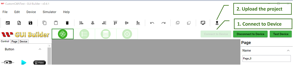
After verifying the functionality with the simulator and confirming that it operates as expected, connect to the Device and upload the Project settings to the Smart Display.
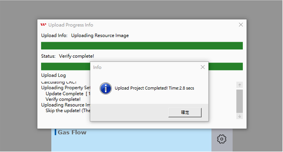
Wait for the Project upload and update process to complete.
Verify Device CAN ID / CAN Data and Widget Interaction
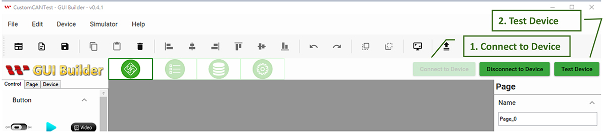
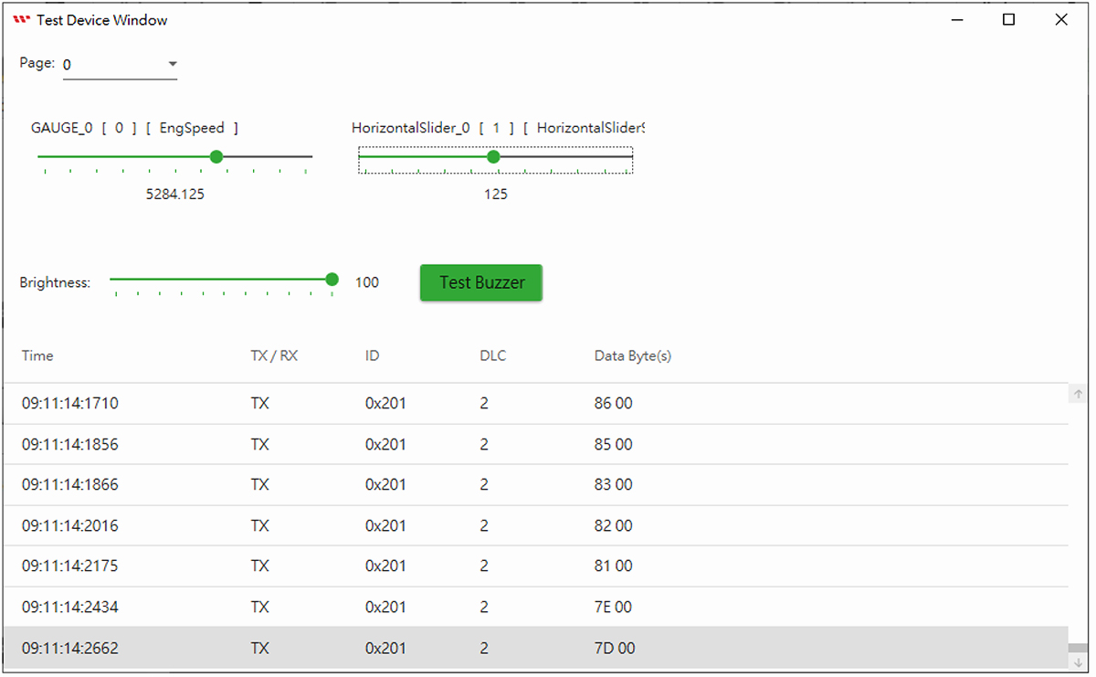
After uploading the Project to the Device, you can further verify the functionality of the Smart Display. Connect GUI Builder to the Device and click "Test Device" to open the Test Device Window and test the interaction between the Host and Device.
Test Device Window
The Test Device Window can simulate the Host sending the corresponding CAN ID and CAN Data according to the DBC configuration. Move the EngSpeed slider to simulate the Host sending EngSpeed data and observe the corresponding Gauge changes on the Smart Display. The CAN data records at the bottom of the window show the CAN ID and CAN Data. You can also operate the Horizontal Slider on the Smart Display to verify whether the data sent by the Device meets the requirements.
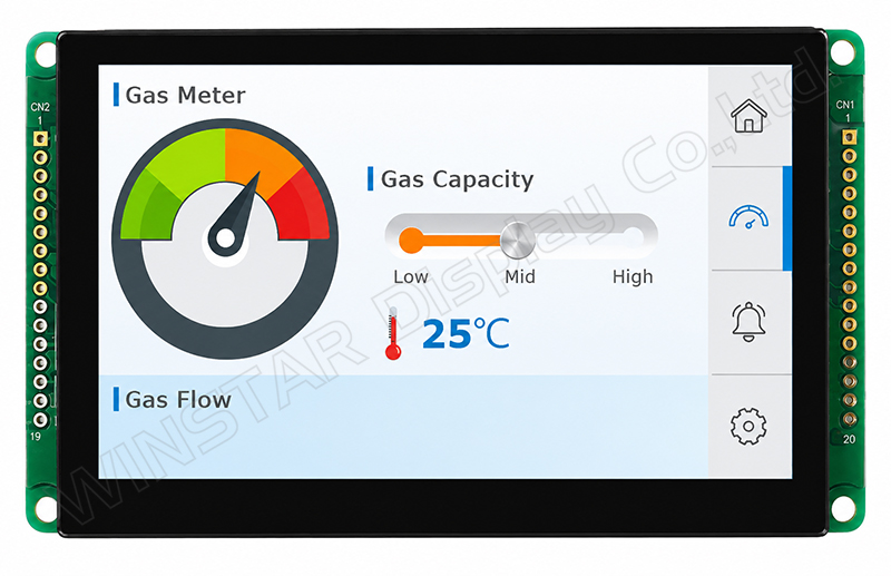
Actual Display on the Smart Display
Custom CAN Command Introduction
The following will describe the command protocol used by Custom CAN. Through these commands, the Host device can easily control the SmartDisplay, including switching pages, adjusting the brightness, or making the buzzer emit sound.
CAN ID Configuration
The following CAN ID settings are used by the command protocol:
- CAN Id format:29 bit
CAN Id:0xEF0000 + 0x7B00 (default channel id. This can be modified through the GUI Builder.)
Command Data Format
Send Command
| Header Byte (1 Byte) |
Length (1 Byte) |
Payload (N byte) |
CRC (2 Byte) |
| Fixed value:0x53 (S) |
Value = 4 + Payload length
Payload max size: 250 |
For data content and length, please refer to Send Command Payload. |
Modbus CRC16 |
Response Command
| Header Byte (1 Byte) |
Length (1 Byte) |
Payload (N byte) |
CRC (2 Byte) |
| Fixed value:0x52 (R) |
Value = 4 + Payload length
Payload max size: 250 |
For data content and length, please refer to Response Command Payload. |
Modbus CRC16 |
Command Payload
The following is the explanation of each command payload.
- Set Brightness:0x6
Send Command
| Command Code |
1 Byte |
0x6 |
| Brightness |
1 Byte |
Brightness value |
Response command
| Command Code |
1 Byte |
0x6 |
| Error Code |
1 Byte |
0:Success
1:Failed |
- Set Buzzer: 0x7
Send Command
| Command Code |
1 Byte |
0x7 |
| Cycle |
1 Byte |
Cycle value |
| High |
1 Byte |
High value |
| Low |
1 Byte |
Low value |
Response command
| Command Code |
1 Byte |
0x7 |
| Error Code |
1 Byte |
0:Success
1:Failed |
- Set Page Index:0x8
Send Command
| Command Code |
1 Byte |
0x8 |
| Page Index |
1 Byte |
Page Index value |
Response command
| Command Code |
1 Byte |
0x8 |
| Error Code |
1 Byte |
0:Success
1:Failed |
- Get Page Count: 0xA
Send Command
Response command
| Command Code |
1 Byte |
0xA |
| Error Code |
1 Byte |
0:Success
1:Failed |
| High |
1 Byte |
Page Count value |
- Get Current Page Index:0xF
Send Command
Response command
| Command Code |
1 Byte |
0xF |
| Error Code |
1 Byte |
0:Success
1:Failed |
| Page Index |
1 Byte |
Page Index value |
- Set Device State:0x20
Send Command
| Command Code |
1 Byte |
0x20 |
| Device State |
1 Byte |
0: ConfigMode
1: DisplayMode |
Response command
| Command Code |
1 Byte |
0x20 |
| Error Code |
1 Byte |
0:Success
1:Failed |
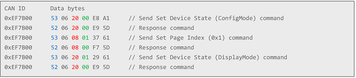
Transmission Example

When switching pages, first set the Device State to ConfigMode, and then send the page switching command. After the page switching command is completed, set the Device State back to DisplayMode. The command sequence is as follows:
Simplifying CAN HMI Development with Custom CAN ID
With the Custom CAN ID protocol, users can define CAN IDs and CAN Data through a standard DBC file and use Smart Display GUI Builder to associate Messages/Signals with the corresponding Widgets, enabling CAN data to be integrated with the HMI interface. For applications that do not require more comprehensive communication protocols such as CANopen or J1939, Custom CAN ID provides a simpler approach to integrating a Host with a Smart Display based on the DBC configuration.
Before connecting to an actual Smart Display device, users can also use the simulation features in Smart Display GUI Builder to verify the interaction between the DBC configuration, CAN data, and Widgets.