
Home Products TFT LCD Display Bar TFT LCD Display WFN0880A2S0YAMNA000

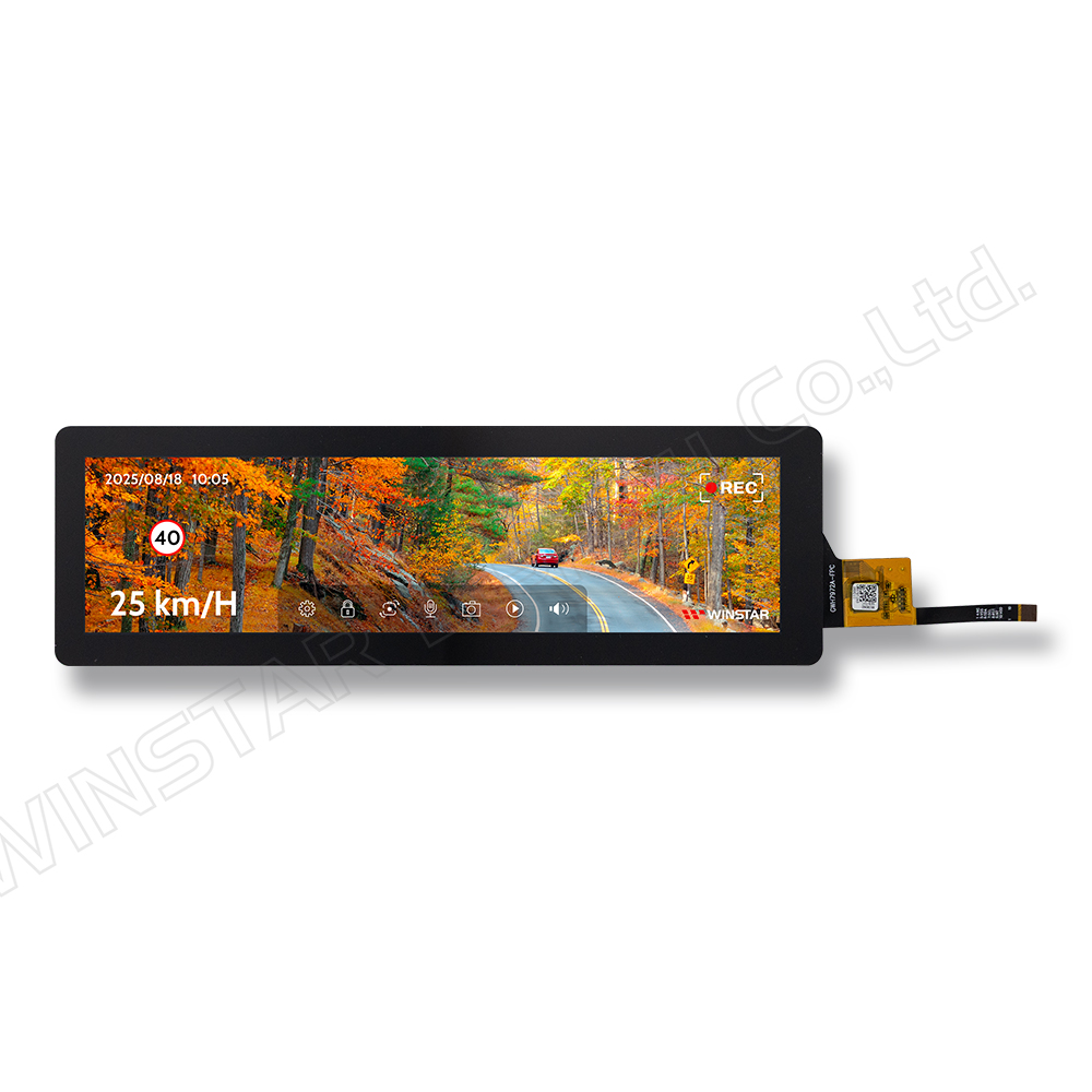
480x1920 8.8-inch Bar Type IPS TFT-LCD with PCAP Touch

Model No. WFN0880A2S0YAMNA000

►Size : 8.8" TFT LCD
►Resolution : 480x1920 pixels
►View Direction : IPS
►Interface : MIPI DSI
►Driver IC:OTA7290N-C
►Control-Board :No
►Brightness (cd/m²) : 850
►Frame Through Hole : No
►Touch Screen : Projected capacitive touch screen (PCAP) + Optical Bonding
►Touch Points: 5

Description

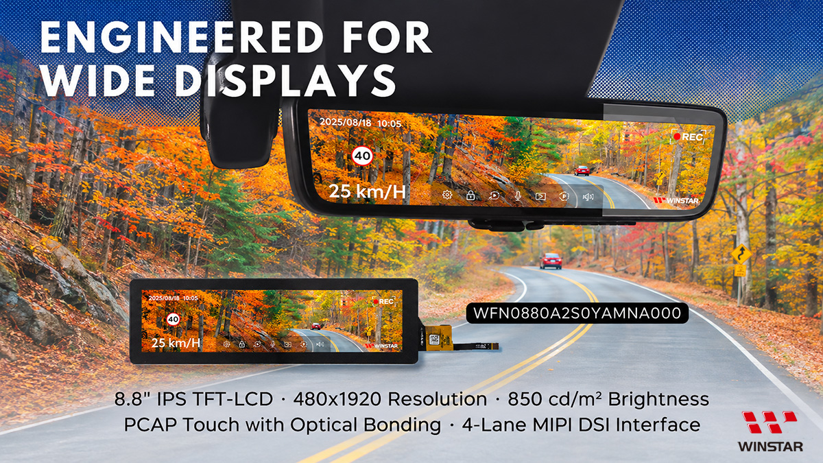
WFN0880A2S0YAMNA000 is an 8.8-inch bar-type IPS TFT-LCD display with a resolution of 480x1920 pixels. Its elongated display format is suitable for horizontal layouts, including control panels, list-based content, and information displays.

The IPS panel provides wide viewing angles of 80°/80°/80°/80° (L/R/U/D, typical). The module integrates a projected capacitive touch panel (PCAP) with optical bonding, using the GT928 touch controller and supporting up to 5-point multi-touch.

The display uses the OTA7290N-C driver IC and a 4-lane MIPI DSI interface, with a 2-lane configuration available as an option. It provides a brightness of 850 cd/m². The module dimensions are 241.3 × 74.3 × 8.7 mm.

The operating temperature range is -20°C to +70°C, with a storage temperature range of -30°C to +80°C.

Applications: Audio/visual equipment, industrial machinery, smart appliances, medical instruments, and systems requiring bar-type displays.

8.8-inch IPS TFT LCD Display with 850 cd/m² Brightness, 4-Lane MIPI DSI and PCAP Touch – WFN0880A2S0YAMNA000

DRAWING

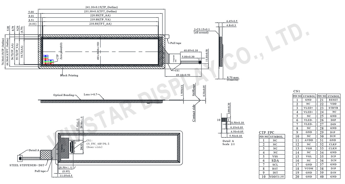
WFN0880A2S0YAMNA000 - Contour Drawing

SPECIFICATIONS

General Specifications

Item Dimension Unit
Size 8.8 inch
Dot Matrix 480 × R.G.B. × 1920 dots
Module dimension 241.3 × 74.3 × 8.7 mm
Active area 218.88 × 54.72 mm
Pixel pitch 0.114 × 0.114 mm
LCD type TFT, Normally black, Transmissive
Viewing angle 80/80/80/80
Backlight Type LED, Normally White
TFT Driver IC OTA7290N-C or Equivalent
TFT Interface 4 Lanes MIPI (2-Lanes Optional)
CTP Driver IC GT928 or equivalent
CTP Interface I2C
CTP FW Version 66
CTP Resolution 480*1920
CTP Support Operation Support 5 finger touch
Touch Panel Projected Capacitive Touch Panel (PCAP)
Surface Glare

Absolute Maximum Ratings

Item Symbol Min Typ Max Unit
Operating Temperature TOP -20 - 70 ℃
Storage Temperature TST -30 - 80 ℃

Electrical Characteristics

TFT LCD Module

Item Symbol Min. Typ. Max. Unit
Supply Voltage VDD 3.0 3.3 3.6 V
VGH 17.0 18.0 19.0 V
VGL -11 -10 -9 V
AVDD 11.8 12 12.2 V
VCOM VCOM 4.5 4.88 5.2 V
Input signal voltage ViH 0.7 VDD - VDD V
ViL 0 - 0.3 VDD V
Output signal voltage VoH 0.8 VDD - - V
VoL 0 - 0.2 VDD V
Current of power supply IDD - 25 38 mA
IADD - 13.5 25 mA
IGH - 3 4.5 mA
IGL - -3 -4.5 mA
Ivcom - 23 35 uA
Supply CTP VDDT3.3V 2.8 - 3.3 V
IDDT3.3V - 13.4 21.0 mA

Interface Pin Function

LCM PIN Definition

Pin No. Symbol I/O Function
1 GND P Ground
2 NC --- No connection
3 VLED+ P LED Anode
4 VLED+ P LED Anode
5 NC --- No connection
6 VLED- P LED Cathode
7 VLED- P LED Cathode
8 NC --- No connection
9 GND P Ground
10 NC --- No connection
11 AVDD P Power supply for analog circuit
12 NC --- No connection
13 VGH P Power supply for analog circuit
14 NC --- No connection
15 VGL P Power supply for analog circuit
16 NC --- No connection
17 GND P Ground
18 VCOM P Power supply for common voltage
19 GND P Ground
20 GND P Ground
21 RESET I Global reset
22 VDD P Power supply for digital circuits
23 STBYB I Standby mode, Normally pulled high
STBYB = “1”, normal operation
STBYB = “0”, timing controller, source driver will turn off, all output are High-Z
24 NC - No connection
25 GND P Ground
26 D0P I MIPI Data Input Lane0 positive-end
27 D0N I MIPI Data Input Lane0 negtive-end
28 GND P Ground
29 D1P I MIPI Data Input Lane1 positive-end
30 D1N I MIPI Data Input Lane1 negtive-end
31 GND P Ground
32 CLKP I MIPI Clock Input positive-end
33 CLKN I MIPI Clock Input negtive-end
34 GND P Ground
35 D2P I MIPI Data Input Lane2 positive-end
36 D2N I MIPI Data Input Lane2 negtive-end
37 GND P Ground
38 D3P I MIPI Data Input Lane3 positive-end
39 D3N I MIPI Data Input Lane3 negtive-end
40 GND P Ground
 

CTP PIN Definition

Pin Symbol Function
1 NC No connection
2 NC No connection
3 NC No connection
4 NC No connection
5 VSS Ground for analog circuit
6 SDA I2C data input and output
7 SCL I2C clock input
8 RST External Reset, Low is active
9 INT External interrupt to the host
10 VDDT3.3V Power Supply : +3.3V
go top
close

We value your privacy

By clicking "Allow All Cookies", you agree to the storing of cookies on your device to enhance site navigation, analyse site usage, and assist in our marketing and performance efforts. You can find further information this subject in our policy.

We value your privacy

Winstar and certain third parties use cookies on www.winstar.com.tw. The details regarding the types of
cookies, their purpose and the third parties involved are described below and in our Cookie Policy.
Please click on “Allow All” to consent to our usage of cookies in order to have the best possible
experience on our websites. You can also set your preferences or reject cookies (except for strictly
necessary cookies).

Manage Consent Preferences

Always Active
Essential Cookies

These cookies are essential in order to enable you to move around the website and use its
features, such as setting your privacy preferences, logging in or filling in forms.

Analytics Cookies

Also known as “statistics cookies,” these cookies collect information about how you use a website, like which pages you visited and which links you clicked on. See Detail