The WF70A9SWAGDNB0 is a high-brightness 7-inch wide-temperature IPS TFT-LCD display featuring a projected capacitive touch screen, boasting a resolution of 800x480 pixels. This module incorporates HX8249-A and HX8678-C driver ICs, supporting a 24-bit RGB interface. The TFT-LCD is equipped with IPS technology, offering advantages such as a wide viewing angle of Left: 80 / Right: 80 / Up: 80 / Down: 80 degrees (typical), a contrast ratio of 1000:1 (typical value), and a high brightness of 800 nits (typical value) on a glare surface panel, with an aspect ratio of 15:9.
The PCAP touch screen is integrated with the ILI2511 IC, supporting a USB interface (also available for I2C) and multi-touch functionality.
The WF70A9SWAGDNB0 operates with a supply voltage (VCC) ranging from 2.7V to 3.6V, with a typical value of 3.3V. It can function in temperatures ranging from -30℃ to +80℃ and can be stored in temperatures from -40℃ to +85℃.
This 7-inch IPS display module is well-suited for deployment in various medical and industrial control equipment. It finds applications in medical instruments, diagnostic devices, industrial automation robots, control boxes, and maintenance equipment. These displays are integral in presenting diverse medical, control, and maintenance data and information. Widely utilized in the medical and industrial control fields, these 7-inch IPS displays enhance the visual experience and functionality of equipment, making them a valuable component in a variety of applications.
SPECIFICATIONS
Interface
1.LCM PIN Definition
| Pin |
Symbol |
Function |
| 1-4 |
NC |
No connection |
| 5 |
GND |
Power Ground |
| 6 |
NC |
No connection |
| 7 |
VCC |
Power voltage |
| 8 |
MODE |
Input timing mode selection.
| MODE |
Function |
Note |
| 0 |
DE only |
- |
| 1 |
HS+VS |
Default |
|
| 9 |
DE |
Data enable signal for TTL mode. |
| 10 |
VS |
Vertical sync input |
| 11 |
HS |
Horizontal sync input |
| 12 |
B7 |
Blue data(MSB) |
| 13 |
B6 |
Blue data |
| 14 |
B5 |
Blue data |
| 15 |
B4 |
Blue data |
| 16 |
B3 |
Blue data |
| 17 |
B2 |
Blue data |
| 18 |
B1 |
Blue data |
| 19 |
B0 |
Blue data(LSB) |
| 20 |
G7 |
Green data(MSB) |
| 21 |
G6 |
Green data |
| 22 |
G5 |
Green data |
| 23 |
G4 |
Green data |
| 24 |
G3 |
Green data |
| 25 |
G2 |
Green data |
| 26 |
G1 |
Green data |
| 27 |
G0 |
Green data(LSB) |
| 28 |
R7 |
Red data(MSB) |
| 29 |
R6 |
Red data |
| 30 |
R5 |
Red data |
| 31 |
R4 |
Red data |
| 32 |
R3 |
Red data |
| 33 |
R2 |
Red data |
| 34 |
R1 |
Red data |
| 35 |
R0 |
Red data (LSB) |
| 36 |
GND |
Power Ground |
| 37 |
DCLK |
Sample clock |
| 38 |
GND |
Power Ground |
| 39 |
L/R |
Horizontal shift direction (source output) selection.
| L/R |
Source output sequence and data order |
Note |
| 1 |
Left to right |
Default |
| 0 |
Right to left |
- |
|
| 40 |
U/D |
Vertical shift direction (gate output) selection.
| U/D |
Function |
Note |
| 1 |
Top→bottom |
Default |
| 0 |
Bottom→top |
- |
|
| 41 |
NC |
No connection |
| 42 |
NC |
No connection |
| 43 |
NC |
No connection |
| 44 |
RESET |
Reset pin. The chip is in reset state when RESETB=0. |
| 45 |
NC |
No connection |
| 46 |
NC |
No connection |
| 47 |
DITHB |
STBYB Standby mode setting pin. The chip is in standby mode when STBYB=0. |
| 48 |
GND |
Power Ground |
| 49 |
NC |
No connection |
| 50 |
NC |
No connection |
2.Backlight PIN Definition
| Pin |
Symbol |
Description |
| 1 |
VLED+ |
Red, LED_ Anode |
| 2 |
VLED- |
Black, LED_ Cathode |
3.PCAP PIN Definition
| Pin |
Symbol |
Function |
| 1 |
USB_VSS |
System ground |
| 2 |
USB_VDD 5V |
Power supply |
| 3 |
USB_D+ |
Data + |
| 4 |
USB_D- |
Data - |
| 5 |
VSS |
System ground |
| 6 |
SDA |
I2C data input and output |
| 7 |
SCL |
I2C clock input |
| 8 |
RST |
External Reset, Low is active |
| 9 |
INT |
External interrupt to the host |
| 10 |
VDDT 3.3 |
Power supply |
Note: Interface can support both USB and I2C,USB is main function
General Specifications
| Item |
Dimension |
Unit |
| Size |
7.0 |
inch |
| Dot Matrix |
800 x RGB x 480(TFT) |
dots |
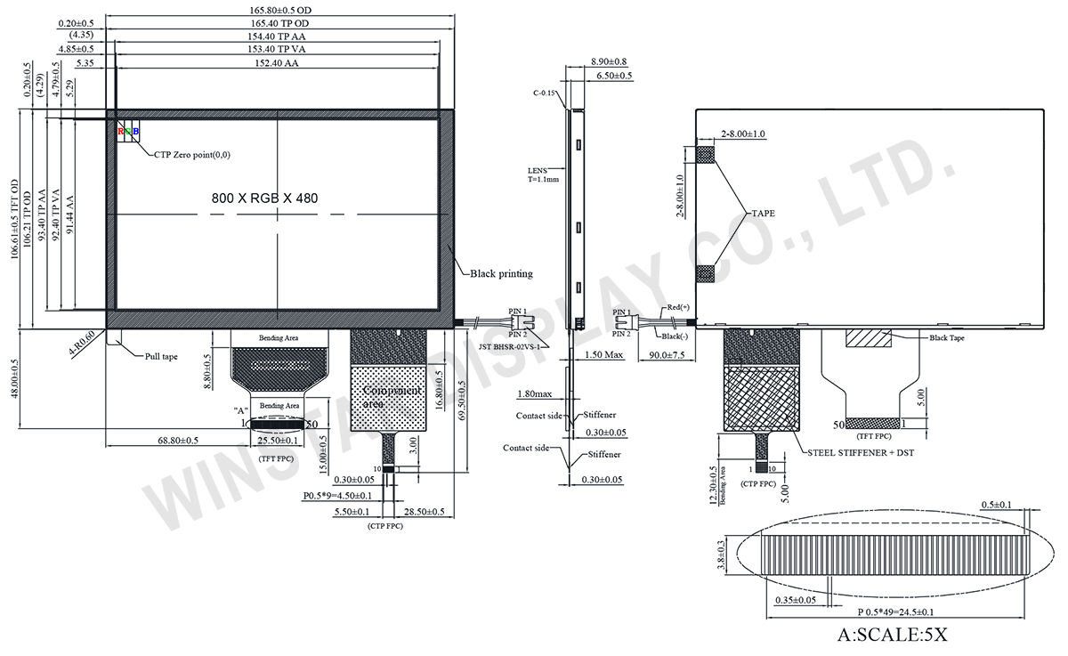
| Module dimension |
165.8 (W) x 106.61 (H) x 8.9(D) |
mm |
| Active area |
152.40 x 91.44 |
mm |
| Pixel pitch |
0.1905 x 0.1905 |
mm |
| LCD type |
TFT, Normally Black, Transmissive |
| View Direction |
80/80/80/80 |
| TFT Interface |
24-bit RGB |
| TFT Driver IC |
HX8249-A + HX8678-C or Equivalent |
| Aspect Ratio |
15:9 |
| Backlight Type |
LED, Normally White |
| PCAP IC |
ILI2511 or equivalent |
| PCAP Interface |
USB (I2C available) |
| PCAP FW Version |
6.0.0.0.0.0.0.1 |
| Touch Panel |
Projected capacitive touch panel (PCAP) |
| Surface |
Anti-Glare |
Absolute Maximum Ratings
| Item |
Symbol |
Min |
Typ |
Max |
Unit |
| Operating Temperature |
TOP |
-30 |
- |
+80 |
℃ |
| Storage Temperature |
TST |
-40 |
- |
+85 |
℃ |
Electrical Characteristics
Operating conditions
| Item |
Symbol |
Min |
Typ |
Max |
Unit |
| Supply Voltage |
Vcc |
2.7 |
3.3 |
3.6 |
V |
| Current of power supply |
Icc |
- |
101 |
150 |
mA |
| Supply PCAP |
USB_VDD 5V |
4.4 |
5.0 |
5.5 |
V |
| IVDD 5V |
- |
83.6 |
126 |
mA |
Search keyword: tft 7", 7 tft lcd, 7" tft lcd, 7 inch tft lcd, tft lcd 7, 7 tft display, 7" tft display, 7 inch tft display, tft display 7"