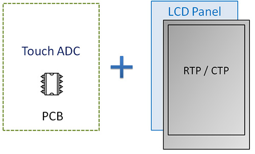
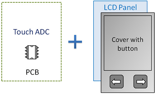
STN LCD modules with touch functionality commonly use a 3-in-1 structure that combines a driver PCB, an STN LCD, and either a resistive touch panel (RTP) or capacitive touch panel (CTP), as shown in Image 1. Another approach combines a driver PCB, an STN LCD, and a membrane switch, as shown in Image 2.
[Image 1]
[Image 2]
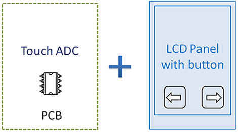
WINSTAR developed a 2-in-1 design that combines the driver PCB and STN LCD. The touch keys are integrated within the LCD viewing area (VA) to improve touch sensitivity, as shown in Image 3.
[Image 3]
Product Features
- Compatible LCD types: TN, STN, FSTN, and VATN.
- Operating voltage: 2.2V to 5.5V.
- Direct one-to-one pin output with selectable active-high or active-low operation.
- Low-cost, simple structure.
- Supports multiple touch ADC ICs.
- Low power consumption in standby mode.
- An external capacitor can be connected to adjust touch sensitivity.
- Supports different IC options for single-touch or multi-touch operation, depending on application requirements.
- Automatic switching between standby and operating modes.
- The IC supports auto-calibration to automatically obtain the reference value.
- PCB + pin connection design supports larger STN LCD modules.
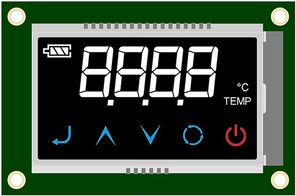
Image 4 shows an ICON-type STN LCD module with capacitive touch keys as an example of this design. In the upper area of the LCD, the ICON patterns are controlled by the controller or driver IC to display the corresponding ICON graphics.
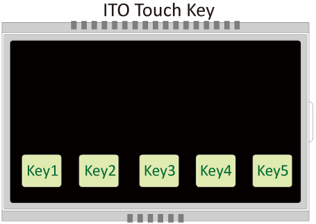
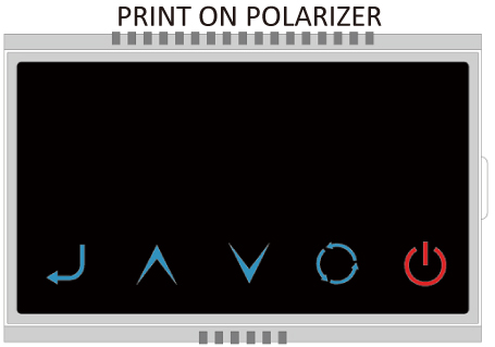
The lower area of the LCD contains five colored ICON patterns created using silkscreen printing, with each ICON incorporating a capacitive touch key. As shown in Image 5, the touch keys use transparent conductive ITO layers formed into rectangular sensor pads on the glass. A polarizer with fixed graphics and color silkscreen printing is placed over the sensor pads, as shown in Image 6. During lamination, the printed graphics on the polarizer must be precisely aligned with the rectangular ITO sensor pads. For positive-mode LCDs, the silkscreen printing is applied to the lower polarizer, while for negative-mode LCDs, it is applied to the upper polarizer. After printing, a transparent protective film is applied over the polarizer to prevent the printed graphics from peeling due to repeated touch.
The driver PCB and STN LCD are connected using pins, while the touch sensor pads use an ICON-type capacitive touch design. With this structure, the display size is not limited to smaller modules, and larger STN LCD modules can also be selected. For larger modules using this structure, however, the touch sensor pads and ICON display areas must be staggered and must not overlap.
[Image 4]
 |
 |
| [Image 5] |
[Image 6] |
Design Requirements for ICON Touch STN LCDs
1. Touch Key Dimensions
Touch keys can be designed in various shapes, although rectangular keys are generally preferred based on human-factor considerations. Touch sensitivity is related to the size and thickness of the ITO sensor pad. A larger sensor pad generally provides higher touch sensitivity. However, once the ITO sensor pad exceeds the size of a fingertip, further increasing the sensor area provides only limited improvement in sensitivity. The ideal ITO sensor pad size is approximately 8–15 mm, and the pad should not be smaller than 8 x 8 mm to reduce the risk of sensing failure.
2. Spacing Between Touch Keys
For designs with multiple touch keys, sufficient spacing must be maintained between the sensor pads to minimize interference. A minimum gap of at least 2 mm is recommended, as shown in Image 7.

[Image 7]
3. Touch Key Layout and Circuit Design
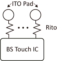
Proper matching between the circuit resistance and the touch driver IC is critical. Lower circuit resistance provides greater flexibility when adjusting touch sensitivity. In contrast, higher circuit resistance limits the available adjustment range and may prevent the desired touch sensitivity from being achieved. As shown in Image 8, the resistance of the ITO (Rito) is significantly higher than that of the conductive traces.
According to Ohm's law, shorter or wider conductive traces have lower resistance. However, if a conductive trace is too wide, it may cause touch detection problems and make sensitivity adjustment more difficult. Therefore, the conductive traces should be kept as short as practical to minimize these potential effects. When using narrower conductive traces, the resistance must still meet the requirements for touch-signal transmission.
[Image 8]
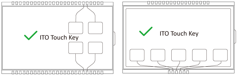
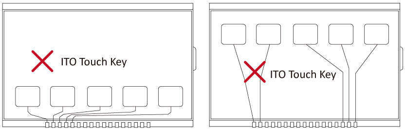
For the touch signal layout, the conductive paths should have the same or closely matched lengths and resistance values to maintain stable and consistent sensing signals. Ideally, the ITO sensor pads should be positioned outside the LCD viewing area and close to the pin-out area, which is the area nearest the interface. Image 9 shows an example of a recommended circuit layout, while Image 10 illustrates a layout that should be avoided because it may result in unstable touch signals.
[Image 9]
[Image 10]
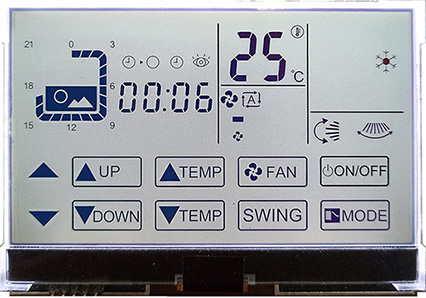
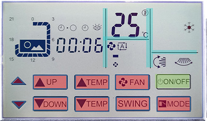
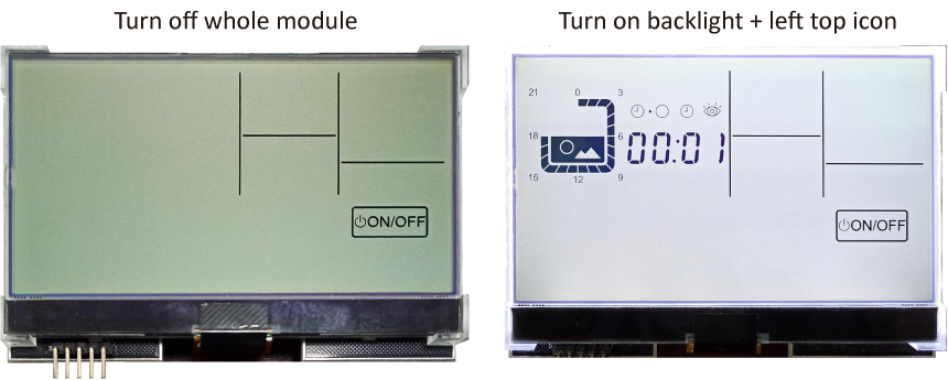
For smaller STN LCDs with touch functionality, such as ICON displays below 4.6 inches or graphic displays below 3.5 inches, WINSTAR offers a more efficient solution using a driver IC that combines both display and touch functions. The IC is bonded directly to the STN LCD panel using COG (Chip-on-Glass) technology, as shown in Images 11 to 13. In these examples, the blue area indicates the silkscreen-printed display area, the green area indicates the silkscreen-printed touch key, and the red area combines the ICON display area with the touch key.
This highly integrated design combines the ADC touch and display functions within a single COG IC, eliminating the need for a separate driver PCB, touch panel, display IC, and touch IC. By shortening the signal path to the driver IC, the COG structure can also improve touch and display performance.
WINSTAR operates its own COG production line and provides fast, high-quality OEM/ODM services for custom display requirements. Through vertically integrated manufacturing and OEM/ODM services, WINSTAR can help shorten the development cycle, reduce costs, enhance product value, and improve product competitiveness.
[Image 11 COG STN-LCD]
[Image 12]
[Image 13]