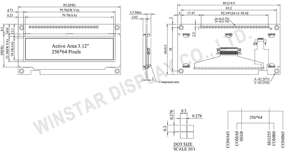
Ana sayfa Ürünler OLED Ekran Grafik OLED Ekran WEN025664B

3.12 inç 256x64 COF OLED Ekran +PCB +Frame

Model No. WEN025664B

►Türü : Grafik
►Yapı : COF+PCB+Frame
►Boyut : 3.12 inç
►256 x 64 dot matrisi
►Kontrolör dahil SSD1322
►3V güç sağlayıcı
►1/64 görev
►Ara yüz : 6800, 8080, SPI
►OLED Rengi: Beyaz / Sarı / Gök Mavisi / Yeşil
►Support Grayscale

Açıklama

WEN025664B model, 3.12 inç çapında ve 256x64 nokta çözünürlüğünde bir COF Grafik OLED'dir. Bu OLED modülü, SSD1322 IC ile entegre edilmiş olup 8-bit 6800/8080 ve 3/4 hat SPI arabirimlerini destekler. Dış çizgi boyutu 89.2 × 44.0 mm, etkin alan boyutu ise 76.78 × 19.18 mm'dir. Ayrıca, 3V mantık besleme voltajını destekleyen 4-bit gri tonlamayı da sağlar. Ekranın %50 kontrol kartında akım, 150mA @3.0V VDD (tipik değer) olup sürücü görevi 1/64'tür.

Modül, müşterilerin uygulamaları için ek PCB geliştirmeye gerek olmadan tel bağlantıları kullanmasına izin veren bir dahili PCB'ye sahiptir. Ayrıca, PCB üzerinde entegre edilmiş VCC devresi müşteri kullanımını basitleştirir. Bu PCB kartı, dört montaj deliği ile donatılmış olup müşterilere modülleri uygulamalarında güvence altına alma kolay bir yöntem sunar. Bu OLED modülü, akıllı ev uygulamaları, tıbbi cihazlar, endüstriyel kontrol vb. için uygundur.

WEN025664B modeli, -40℃ ila +80℃ arasındaki sıcaklıklarda çalışabilir ve depolama sıcaklıkları -40℃ ila +85℃ arasındadır. OLED modülü, 10,000:1 yüksek kontrast oranına sahiptir, bu da geliştirilmiş görüntü kalitesi, daha keskin detaylar ve özellikle düşük ışıklı ortamlarda iyileştirilmiş okunabilirlik sağlar.

Ayrıca, aynı boyutlarda olan OLED paneller çeşitli alternatifler sunar:
  • Metal çerçeve ve PCB olmadan WEX025664B serisi.
  • Metal çerçeve, PCB olmadan ve CTP dokunmatik ekran ile WEX025664B-CTP serisi.
  • Metal çerçeve, PCB ve CTP dokunmatik ekran ile WEN025664B-CTP serisi.

ÇIZIM

3.12 inch 256x64 COF OLED Display With PCB and Frame - WEN025664B

Data source ref: WEN025664BWAP3N0000

AYRINTILAR

Arayüz Pin Fonksiyonlari

Pin
Number
Sembol I/O Fonksiyon
1 VSS P Ground.
2 VDD P Power Supply for Core Logic Circuit
Power supply pin for core logic operation. A capacitor is required to connect between this pin and VSS
3 N.C. P Reserved Pin
The N.C. pin between function pins are reserved for compatible and flexible design.
4 D/C# I Data/Command Control
This pin is Data/Command control pin connecting to the MCU.
When the pin is pulled HIGH, the content at D[7:0] will be interpreted as data.
When the pin is pulled LOW, the content at D[7:0] will be interpreted as command.
5 R/W#
(WR#)
I Read/Write Select or Write
This pin is MCU interface input. When interfacing to a 68XX-series microprocessor, this pin will be used as Read/Write (R/W#) selection input. Pull this pin to “High” for read mode and pull it to “Low” for write mode.
When 80XX interface mode is selected, this pin will be the Write (WR#) input. Data write operation is initiated when this pin is pulled low and the CS# is pulled low.
When serial mode is selected, this pin must be connected to VSS.
6 E/RD# I Read/Write Enable or Read
This pin is MCU interface input.
When interfacing to a 68XX-series microprocessor, this pin will be used as the Enable (E) signal. Read/write operation is initiated when this pin is pulled high and the CS# is pulled low.
When connecting to an 80XX-microprocessor, this pin receives the Read (RD#) signal. Data read operation is initiated when this pin is pulled low and CS# is pulled low.
When serial mode is selected, this pin must be connected to VSS.
7~14 DB0 I/O Host Data Input/Output Bus
These pins are 8-bit bi-directional data bus to be connected to the microprocessor’s data bus.
When serial mode is selected, DB1 will be the serial data input SDIN and DB0 will be the serial clock input SCLK.
DB1
DB2
DB3
DB4
DB5
DB6
DB7
15 NC P Reserved Pin
The N.C. pin between function pins are reserved for compatible and flexible design.
16 RES# I This pin is reset signal input.
When the pin is pulled LOW, initialization of the chip is executed.
Keep this pin pull HIGH during normal operation.
17 CS# I Data/Command Control
This pin is the chip select input connecting to the MCU. The chip is enabled for MCU communication only when CS# is pulled LOW.

18
NC P Reserved Pin
The N.C. pin between function pins are reserved for compatible and flexible design.
19 BS1 I Communicating Protocol Select
These pins are MCU interface selection input. See the following table:
BS:[1:0] Bus Interface Selection
00 4 line SPI
01 3 line SPI
10 8-bit 8080 parallel
11 8-bit 6800 parallel
Note
(1) 0 is connected to VSS
(2) 1 is connected to VDD
20 BS0
21~24 NC P Reserved Pin
The N.C. pin between function pins are reserved for compatible and flexible design.

Mekanik Veri

Kalem Dimension Birim
Nokta Matrisi 256 x 64 Dots
Modül ölçüleri 89.2 × 44.0 × 3.3 Max. mm
Aktif alan 76.78 × 19.18 mm
Nokta boyutu 0.278 × 0.278 mm
Nokta sıklığı 0.3 × 0.3 mm
Display Mode Pasif Matrisli
OLED Rengi Monokrom
Drive Duty 1/64 Duty
Gray Scale 4 bits
IC SSD1322 (COF)
Arayüz 6800, 8080, SPI
Boyut 3.12 inç

Maksimum Değerler

Parameter Sembol Minumum Deger Maksimum Deger Birim
Supply Voltage for Display VDD -0.3 4 V
Çalışma Sıcaklığı TOP -40 80 °C
Saklama Sıcaklığı TSTG -40 85 °C

Elektronik Özellikleri

Kalem Sembol Durum Minumum Deger Tipik Deger Maksimum Deger Birim
Supply Voltage for Logic VDD 2.8 3.0 3.3 V
High Level Input VIH 0.8×VDD VDD V
Low Level Input VIL 0 0.2×VDD V
High Level Output VOH 0.9×VDD VDD V
Low Level Output VOL 0 0.1×VDD V
50% Check Board operating Current IDD VCC =3V 150 300 mA

Search keyword: 256x64 oled, oled 256x64, 3.12 oled, 3.12" oled, 3.12 inç oled, oled 3.12, oled 3.12 inç

go top
close