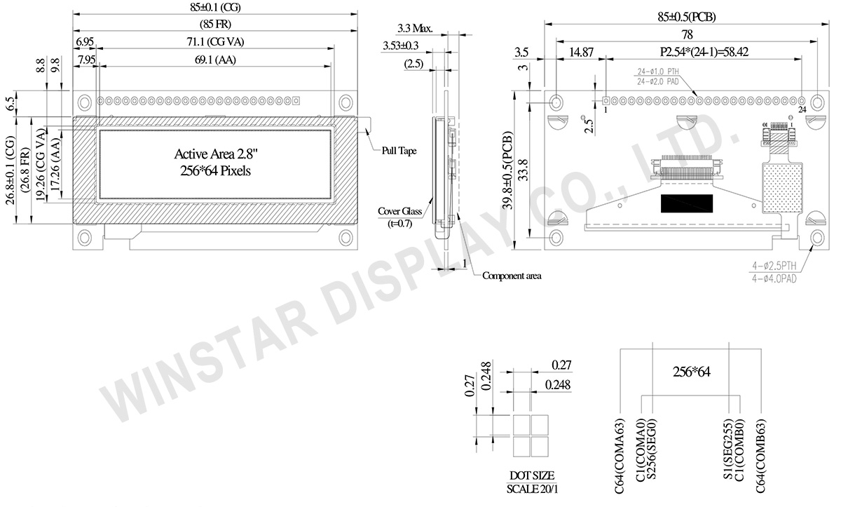
Ana sayfa Ürünler OLED Ekran Dokunmatik Ekran OLED WEN025664A-CTP

2.8 inç 256x64 çözünürlüklü Grayscale COF OLED Ekran, Dokunmatik Panel, PCB ve Çerçeve Desteği

Model No. WEN025664A-CTP

►Türü : Grafik
►Yapı : COF + Çerçeve + PCB
►Boyut : 2.8 inç
►256×64 dot matrisi
►IC:SSD1322
►3V güç sağlayıcı
►1/64 görev döngüsü
►Ara yüz :6800, 8080, SPI
►Dokunmatik Ekran: Kapasitif dokunmatik panelle birlikte (CTP)
►Dokunma Noktaları : 1 Parmak
►OLED Rengi: Beyaz / Sarı
►Gri Tonlama Desteği

Açıklama

WEN025664A-CTP serisi, 256x64 nokta çözünürlüğüne sahip bir kapasitif dokunmatik panel içeren 2.8 inç monokrom grafik COF OLED ekranıdır. SSD1322 IC ile donatılmış olup 6800/8080 8-bit ve 3/4 telli SPI arayüzleri dahil olmak üzere çeşitli arayüzleri destekler. WEN025664A-CTP modülünün boyutları 85.0 × 39.8 mm'dir ve etkin alanı 69.1 × 17.26 mm'dir. Model, I2C arayüzlerini ve 1 noktalı dokunuşu destekleyen FT6336U IC ile projeksiyonlu kapasitif dokunmatik bir panel (PCAP) içerir.

WEN025664A-CTP OLED serisi, 3V güç kaynağı ve 1/64 duty sürüş yöntemi ile çalışır. Grileşmeyi destekler ve 10.000:1 yüksek kontrast oranına sahiptir. Modül, -20°C ila +70°C aralığında çalışabilir ve depolama sıcaklık aralığı -30°C ila +80°C'dir.

Metal çerçeve, PCB kart ve dört vida deliği içeren WEN025664A-CTP, müşteriler için kolay montaj sağlar. PCB kart ile donatılmış olan OLED serisi, müşterilerin ek PCB kartları geliştirmelerine gerek kalmadan uygulamalara kolayca bağlanabilir. Arayüz ayarları ve VDD devrelerinin entegrasyonu kullanım kolaylığını artırır. Ayrıca, PCB üzerindeki dört vida deliği, modülün uygulama ürününe kolayca monte edilmesini sağlar.

WEN025664A-CTP ayrıca aynı OLED paneline sahip ancak dokunmatik panel olmadan bir seçenek sunar. Dokunmatik panel olmayan seçenek için lütfen WEN025664A Model'ini seçin.

ÇIZIM

2.8 inch 256x64 OLED Display with Touch Panel Support Grayscale - WEN025664A-CTP

Data source ref: WEN025664AWPP3D00000

AYRINTILAR

Arayüz Pin Fonksiyonlari

Pin Number Sembol I/O Fonksiyon
1 VSS P Ground.
2 VDD P Power Supply for Core Logic Circuit
Power supply pin for core logic operation. A capacitor is required to connect between this pin and VSS
3 N.C. P Reserved Pin
The N.C. pin between function pins are reserved for compatible and flexible design.
4 D/C# I Data/Command Control
This pin is Data/Command control pin connecting to the MCU.
When the pin is pulled HIGH, the content at D[7:0] will be interpreted as data.
When the pin is pulled LOW, the content at D[7:0] will be interpreted as command.
5 R/W#
(WR#)
I Read/Write Select or Write
This pin is MCU interface input. When interfacing to a 68XX-series microprocessor, this pin will be used as Read/Write (R/W#) selection input. Pull this pin to “High” for read mode and pull it to “Low” for write mode.
When 80XX interface mode is selected, this pin will be the Write (WR#) input. Data write operation is initiated when this pin is pulled low and the CS# is pulled low.
When serial mode is selected, this pin must be connected to VSS.
6 E/RD# I Read/Write Enable or Read
This pin is MCU interface input.
When interfacing to a 68XX-series microprocessor, this pin will be used as the Enable (E) signal. Read/write operation is initiated when this pin is pulled high and the CS# is pulled low.
When connecting to an 80XX-microprocessor, this pin receives the Read (RD#) signal. Data read operation is initiated when this pin is pulled low and CS# is pulled low.
When serial mode is selected, this pin must be connected to VSS.
7~14 DB0 I/O Host Data Input/Output Bus
These pins are 8-bit bi-directional data bus to be connected to the microprocessor’s data bus.
When serial mode is selected, D1 will be the serial data input SDIN and D0 will be the serial clock input SCLK.
DB1
DB2
DB3
DB4
DB5
DB6
DB7
15 NC P Reserved Pin
The N.C. pin between function pins are reserved for compatible and flexible design.
16 RES# I This pin is reset signal input.
When the pin is pulled LOW, initialization of the chip is executed.
Keep this pin pull HIGH during normal operation.
17 CS# I Data/Command Control
This pin is the chip select input connecting to the MCU. The chip is enabled for MCU communication only when CS# is pulled LOW.
18 NC P Reserved Pin
The N.C. pin between function pins are reserved for compatible and flexible design.
19 BS1 I Communicating Protocol Select
These pins are MCU interface selection input. See the following table:
BS[1:0] Interface
00 4 line SPI
01 3 line SPI
10 8-bit 8080 parallel
11 8-bit 6800 parallel

Note
(1) 0 is connected to VSS
(2) 1 is connected to VDD
20 BS0
21 TP_SCK I I2C clock input
22 TP_SDA I I2C data input and output
23 TP_INT I External interrupt to the host
24 TP_RST I External Reset, Low is active

Mekanik Veri

Kalem Ölçü Birim
Nokta Matrisi 256 × 64 Dots
Modül ölçüleri 85.0 × 39.8 ×7.83 mm
Aktif alan 69.1 × 17.26 mm
Nokta boyutu 0.248 × 0.248 mm
Nokta sıklığı 0.27 × 0.27 mm
Display Mode Pasif Matrisli
Display Color Monokrom
Drive Duty 1/64 Duty
OLED IC SSD1322 (COF)
OLED Arayüz 6800, 8080, SPI
Boyut (Köşegen) 2.8 inç
CTP IC FT6336U
Dokunma Noktaları 1
CTP Arayüz I2C
Yüzey Parlama

Maksimum Değerler

Maksimum Değerler

Parameter Sembol Minumum Deger Maksimum Deger Birim
Supply Voltage for Display VDD -0.3 4 V
Çalışma Sıcaklığı TOP -20 +70 °C
Saklama Sıcaklığı TSTG -30 +80 °C

Elektronik Özellikleri

DC Elektronik Özellikleri

Kalem Sembol Durum Minumum Deger Tipik Deger Maksimum Deger Birim
Logic supply voltage VDD 2.8 3.0 3.3 V
High Level Input VIH 0.8×VDD VDD V
Low Level Input VIL 0 0.2×VDD V
High Level Output VOH 0.9×VDD VDD V
Low Level Output VOL 0 0.1×VDD V
50% Check Board operating Current IDD VDD =3V 125 250 mA

Search keyword: 256x64 oled, oled 256x64, 2.8 oled, 2.8" oled, 2.8 inç oled, oled 2.8"

go top
close