Ana sayfa Ürünler OLED Ekran Dokunmatik Ekran OLED WEP012864Q-CTP

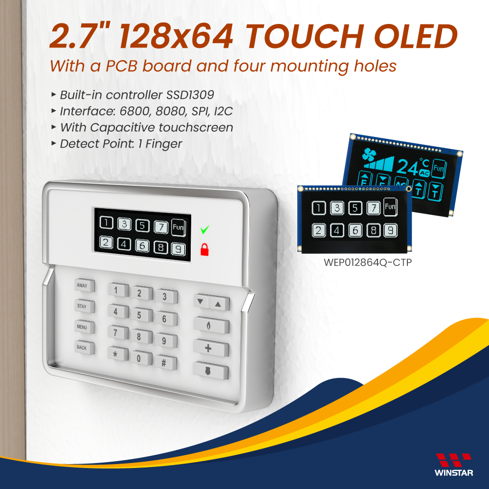
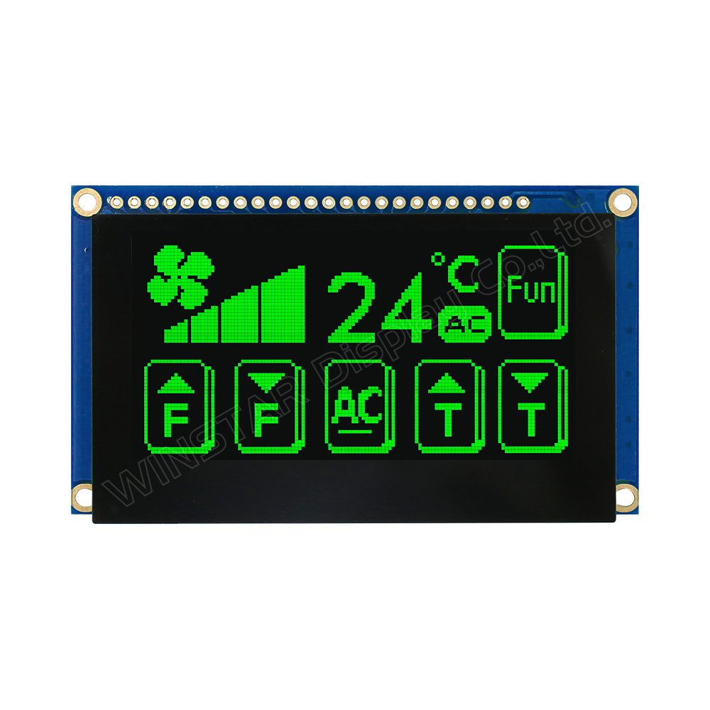
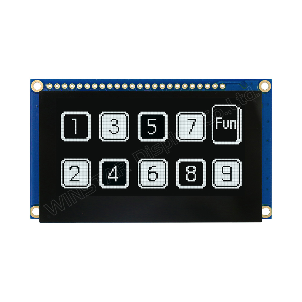
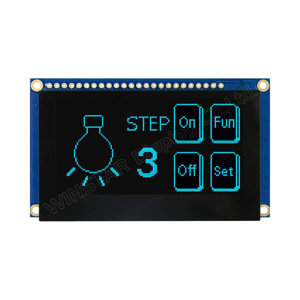
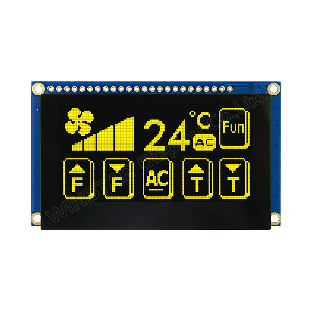
2.7", 128x64 Kapasitif Dokunmatik Panel OLED Ekran Modülleri Frame +PCB

Model No. WEP012864Q-CTP

►Türü : Grafik
►Yapı : COG + Frame + PCB
►Boyut : 2.7 inç
►128 x 64 dot matrisi
►IC:SSD1309
►3V güç sağlayıcı
►1/64 görev
►Ara yüz : 6800, 8080, SPI, I2C
►Dokunmatik Panel: Kapasitif Dokunmatik Panel (CTP)
►Dokunma Noktaları : 1 Parmak
►OLED Rengi: Beyaz / Sarı / Gök Mavisi / Yeşil

Açıklama

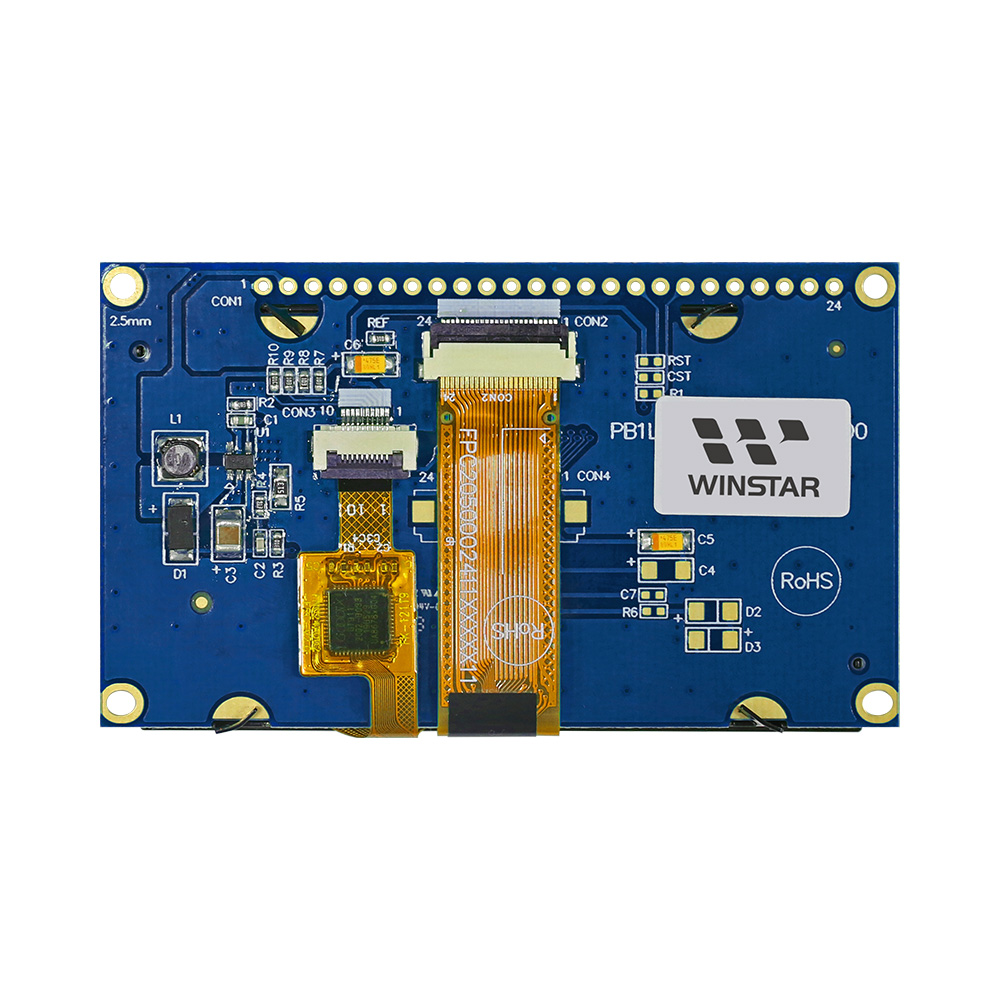
WEP012864Q-CTP model, 2,7 inç boyutunda COG Grafik OLED, Kapasitif Dokunmatik Panel ile birlikte gelir ve 128x64 pikselden oluşur. Bu OLED modülü, SSD1309 IC ile entegredir; 6800/8080 8-bit paralel, I2C ve 4-Tel SPI arabirimini destekler, mantık besleme voltajı 3V, %50 Kontrol Kartı akımı ile ekran 175mA @3.0V VDD (tipik değer), sürücü görevi 1/64'tür. Bu modelde Modülde Kapasitif Dokunmatik Panel bulunur; I2C arabirimini destekleyen GT911 IC ile entegre edilmiştir, CTP için bir tespit noktası ve normal parlamalı yüzeyli cam bulunur. Modülde, müşterilerin ek PCB geliştirmelerine gerek olmadan kablo bağlantısı kullanmaları için bir PCB kartı bulunur. Ayrıca, müşterilerin kullanımını kolaylaştırmak için PCB üzerine VCC devresi entegre ettik.

WEP012864Q-CTP model, modülde bir PCB bulunan COG OLED bir ekranı temsil eder. Bu dört montaj deliği olan PCB, müşterilerin modülleri uygulamalarına kolayca sabitlemeleri için basit bir yöntemdir. Bu OLED modülü, akıllı ev uygulamaları, tıbbi cihazlar, endüstriyel kontrol vb. için uygundur. WEP012864Q-CTP modelinin çalışma sıcaklığı -20℃ ile +70℃ arasında değişir; depolama sıcaklıkları ise -30℃ ile +80℃ arasındadır.

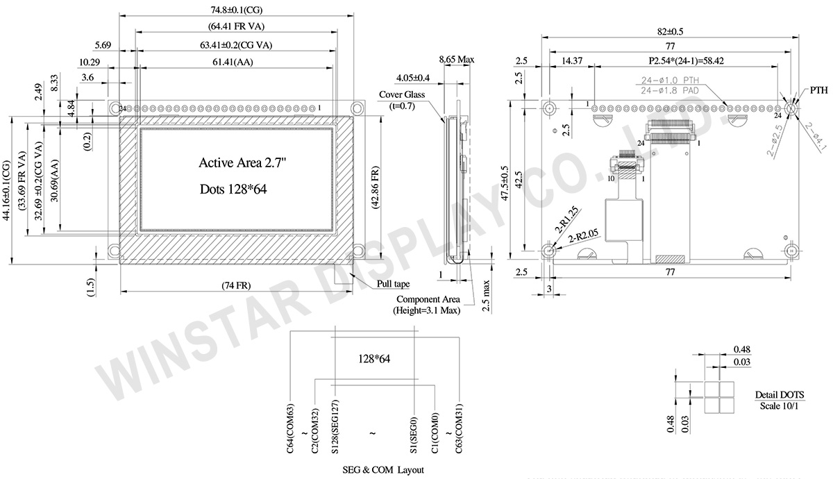
ÇIZIM

2.7 inch 128x64 COG Capacitive Touch OLED Display with Frame +PCB - WEP012864Q-CTP
 

Data source ref: WEP012864QWPP3D00000

AYRINTILAR

Arayüz Pin Fonksiyonlari

No. Sembol Fonksiyon
1 VSS Ground.
2 VDD Power supply pin for core logic operation
3 NC No connection
4 D/C# This pin is Data/Command control pin connecting to the MCU.
When the pin is pulled HIGH, the data at D[7:0] will be interpreted as data.
When the pin is pulled LOW, the data at D[7:0] will be transferred to a command register.
In I2C mode, this pin acts as SA0 for slave address selection.
5 R/W#
(WR#)
This pin is read / write control input pin connecting to the MCU interface.
When 6800 interface mode is selected, this pin will be used as Read/Write (R/W#) selection input. Read mode will be carried out when this pin is pulled HIGH and write mode when LOW.
When 8080 interface mode is selected, this pin will be the Write (WR#) input. Data write operation is initiated when this pin is pulled LOW and the chip is selected.
When serial or I2C interface is selected, this pin must be connected to VSS.
6 E(/RD#) This pin is MCU interface input.
When 6800 interface mode is selected, this pin will be used as the Enable (E) signal.
Read/write operation is initiated when this pin is pulled HIGH and the chip is selected.
When 8080 interface mode is selected, this pin receives the Read (RD#) signal. Read operation is initiated when this pin is pulled LOW and the chip is selected.
When serial or I2C interface is selected, this pin must be connected to VSS.
7-14 D0~D7 These pins are bi-directional data bus connecting to the MCU data bus.
Unused pins are recommended to tie LOW.
When serial interface mode is selected, D0 will be the serial clock input: SCLK; D1 will be the serial data input: SDIN and D2 should be kept NC.
When I2C mode is selected, D2, D1 should be tied together and serve as SDAout, SDAin in application and D0 is the serial clock input, SCL.
15 NC No connection
16 RES# This pin is reset signal input.
When the pin is pulled LOW, initialization of the chip is executed.
Keep this pin pull HIGH during normal operation.
17 CS# This pin is the chip select input connecting to the MCU.
The chip is enabled for MCU communication only when CS# is pulled LOW (active LOW).
18 NC No connection
19 BS2 MCU bus interface selection pins. Select appropriate logic setting as described in the following table. BS2 and BS1 are pin select
  BS1 BS2
I2C 1 0
4-wire Serial 0 0
8-bit 68xx Parallel 0 1
8-bit 80xx Parallel 1 1
Note
(1) 0 is connected to VSS
(2) 1 is connected to VDD
20 BS1
21 TP_SCK I2C clock signal
22 TP_SDA I2C data signal
23 TP_INT External interrupt signal, active low
24 TP_RST External reset signal, active low

Mekanik Veri

Kalem Ölçü Birim
Nokta Matrisi 128 x 64
Modül ölçüleri 82.0 × 47.5 × 8.65 Max. mm
Aktif alan 61.41 × 30.69 mm
Nokta boyutu 0.45 × 0.45 mm
Nokta sıklığı 0.48 × 0.48 mm
Display Mode Pasif Matrisli
Display Color Monokrom
Drive Duty 1/64 Duty
IC SSD1309
Arayüz 6800,8080,4-Wire SPI,I2C
Boyut (Köşegen) 2.7 inç
CTP IC GT911
Dokunma Noktaları 1
CTP Arayüz I2C
Yüzey Parlama

Maksimum Değerler

Parameter Symbol Minumum Deger Maksimum Deger Birim
Supply Voltage for Logic VDD -0.3 4 V
Çalışma Sıcaklığı TOP -20 +70 °C
Saklama Sıcaklığı TSTG -30 +80 °C

Elektronik Özellikleri

DC Elektronik Özellikleri

Kalem Sembol Durum Minumum Deger Tipik Deger Maksimum Deger Birim
Supply Voltage for Logic VDD 2.8 3.0 3.3 V
High Level Input VIH 0.8×VDD V
Low Level Input VIL 0.2×VDD V
High Level Output VOH 0.9×VDD V
Low Level Output VOL 0.1×VDD V
50% Check Board operating Current VDD =3V 175 350 mA
 

Dokunmatik Panel kontrol GT911

Kalem Sembol Minumum Deger Tipik Deger Maksimum Deger Birim
Input High Volt. VIH 0.75×VDD   VDD+0.3 V
Input Low Volt. VIL -0.3 0.25×VDD V
Output High Volt. VOH 0.85×VDD V
Output Low Volt. VOL 0.15×VDD V

Search keyword: 128x64 oled, oled 128x64, 2.7 oled, 2.7 inç oled, oled 2.7
go top
close