Strona główna Produkty Wyświetlacz OLED Graficzne Wyświetlacz OLED WEP012864U

2.7-calowy wyświetlacz COG OLED o 128x64 ze wsparciem dla skali szarości z PCB i ramką

Numer modelu WEP012864U

►Typ: graficzny
►Struktura: COG + ramki + PCB
►Rozmiar: 2.7"
►128 x 64 matryca punktowa
►IC:SSD1357
►zasilanie 3V
►wypełnienie 1/64
►Interfejs: 6800, 8080, SPI, I2C
►Kolor wyświetlacza: biały / żółto
►Obsługiwana skala szarości

Opis

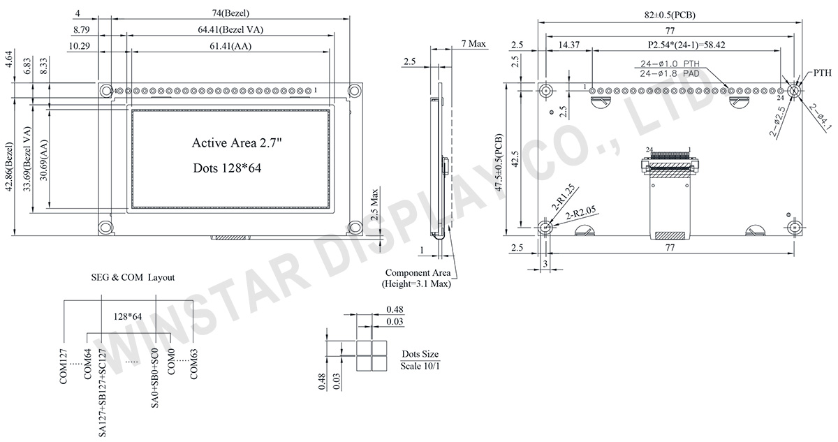
WEP012864U to graficzny wyświetlacz OLED o strukturze COG o rozdzielczości 128x64 pikseli i aktywnej powierzchni 2,7 cala (61,41 × 30,69 mm). Moduł jest wyposażony w układ SSD1357, obsługujący interfejsy 6800/8080 8-bitowych, 4-przewodowy SPI, a także I2C. Wyświetlacz obsługuje skalę szarości 4-bitową, z napięciem logicznym 3V i cyklem pracy 1/64.

Seria OLED WEP012864U zawiera ramkę metalową i płytę PCB, która łatwo łączy się z aplikacją za pomocą przewodów. Klienci nie są zobowiązani do opracowywania dodatkowych płyt PCB, ponieważ integruje ustawienia interfejsu i obwody VCC, upraszczając doświadczenie użytkownika. Płyta PCB została zaprojektowana z czterema otworami na śruby, ułatwiając instalację modułu na produkcie aplikacyjnym.

Ten moduł OLED charakteryzuje się wysokim współczynnikiem kontrastu 10 000:1, co pozwala na bardziej dynamiczne i głębokie czernie, a także jaśniejsze biel. To prowadzi do poprawy jakości obrazu, ostrzejszych detali i lepszej czytelności. Moduł działa w zakresie temperatur od -40℃ do 80℃, a temperatura przechowywania wynosi od -40℃ do 85℃.

Idealny do zastosowań w urządzeniach ściennych/licznikach, aplikacjach domowych, systemach finansowych-POS, systemach Cloud/IoT, inteligentnych urządzeniach technologicznych, systemach energetycznych, systemach komunikacyjnych, instrumentach medycznych, itp.

Dodatkowo, podobne panele OLED są dostępne w serii WEO012864U bez ramki metalowej i PCB, oraz w serii WEF012864U z ramką metalową, ale bez PCB. Jeśli masz wymagania dotyczące funkcji dotykowej, rozważ serię WEP012864U-CTP.

Rysunek

WEP012864U

Data source ref:WEP012864ULAP3N00000

Specyfikacja

Funkcja pinów interfejsu

No. Symbol Funkcja
1 VSS This is a ground pin.
2 VDD Power supply pin for core logic operation
3 NC Reserved Pin
The N.C. pin between function pins is reserved for compatible and flexible design.
4 D/C# This pin is Data/Command control pin connecting to the MCU.
When the pin is pulled HIGH, the data at D[7:0] will be interpreted as data.
When the pin is pulled LOW, the data at D[7:0] will be transferred to a command register.
In I2C mode, this pin acts as SA0 for slave address selection.
5 R/W#
(WR#)
This pin is read / write control input pin connecting to the MCU interface.
When 6800 interface mode is selected, this pin will be used as Read/Write (R/W#) selection input. Read mode will be carried out when this pin is pulled HIGH and write mode when LOW.
When 8080 interface mode is selected, this pin will be the Write (WR#) input. Data write operation is initiated when this pin is pulled LOW and the chip is selected.
When serial or I2C interface is selected, this pin must be connected to VSS.
6 E/RD# This pin is MCU interface input.
When 6800 interface mode is selected, this pin will be used as the Enable (E) signal.
Read/write operation is initiated when this pin is pulled HIGH and the chip is selected.
When 8080 interface mode is selected, this pin receives the Read (RD#) signal. Read operation is initiated when this pin is pulled LOW and the chip is selected.
When serial or I2C interface is selected, this pin must be connected to VSS.
7 DB0 These pins are bi-directional data bus connecting to the MCU data bus.
Unused pins are recommended to tie LOW.
When serial interface mode is selected, D0 will be the serial clock input: SCLK; D1 will be the serial data input: SDIN.
When I2C mode is selected, D2, D1 should be tied together and serve as SDAout, SDAin in application and D0 is the serial clock input, SCL.
8 DB1
9 DB2
10 DB3
11 DB4
12 DB5
13 DB6
14 DB7

15
NC No connection.
16 RES# This pin is reset signal input.
When the pin is pulled LOW, initialization of the chip is executed.
Keep this pin pull HIGH during normal operation.

17
CS# Chip Select
This pin is the chip select input. The chip is enabled for MCU communication only when CS# is pulled low.
18 NC No connection.
19 BS2 Communicating Protocol Select.
These pins are MCU interface selection input. See the following table:
  BS1 BS2
I2C 1 0
4-wire Serial 0 0
8-bit 8080 Parallel 1 1
8-bit 6800 Parallel 0 1
20 BS1
21 NC No connection.
22 NC No connection.
23 NC No connection.
24 NC No connection.

Dane mechaniczne

Rzecz Wymiar Jednostka
Matryca punktowa 128 x 64 punktów
Wymiary modułu 82.0 × 47.5 × 7 Max. mm
Obszar aktywny 61.41 × 30.69 mm
Wielkość piksela 0.45 × 0.45 mm
Raster pomiędzy pikselami 0.48 × 0.48 mm
Tryb wyświetlania matryca
Kolor wyświetlacza Monochromatyczny
Drive Duty 1/64 Duty
Skala szarości 4 bits
IC SSD1357
Interfejs 6800, 8080, SPI, I2C
Rozmiar 2.7 cale

Bezwzględne oceny maksymalne

Parameter Symbol Minimalna wartość Maksymalna wartość Jednostka
Supply Voltage for Logic VDD -0.3 4.0 V
Operating Temperature TOP -40 80 °C
Storage Temperature TSTG -40 85 °C

Parametry elektryczne

Rzecz Symbol Stan Minimalna wartość Typowa wartość Maksymalna wartość Jednostka
Supply Voltage for Logic VDD 2.8 3.0 3.3 V
High Level Input VIH 0.8×VDD V
Low Level Input VIL 0.2×VDD V
High Level Output VOH 0.9×VDD V
Low Level Output VOL 0.1×VDD V
Display 50% Pixel on IDD VDD =3V 120 180 mA
go top
close