私たちはあなたのプライバシーを大切にします
「すべてのクッキーを許可」をクリックすると、サイトのナビゲーションを向上させ、サイト使用状況を分析し、マーケティングおよびパフォーマンスの取り組みを支援するために、クッキーをデバイスに保存することに同意したことになります。この件に関する詳細情報は、ポリシーをご覧ください。プライバシーポリシー

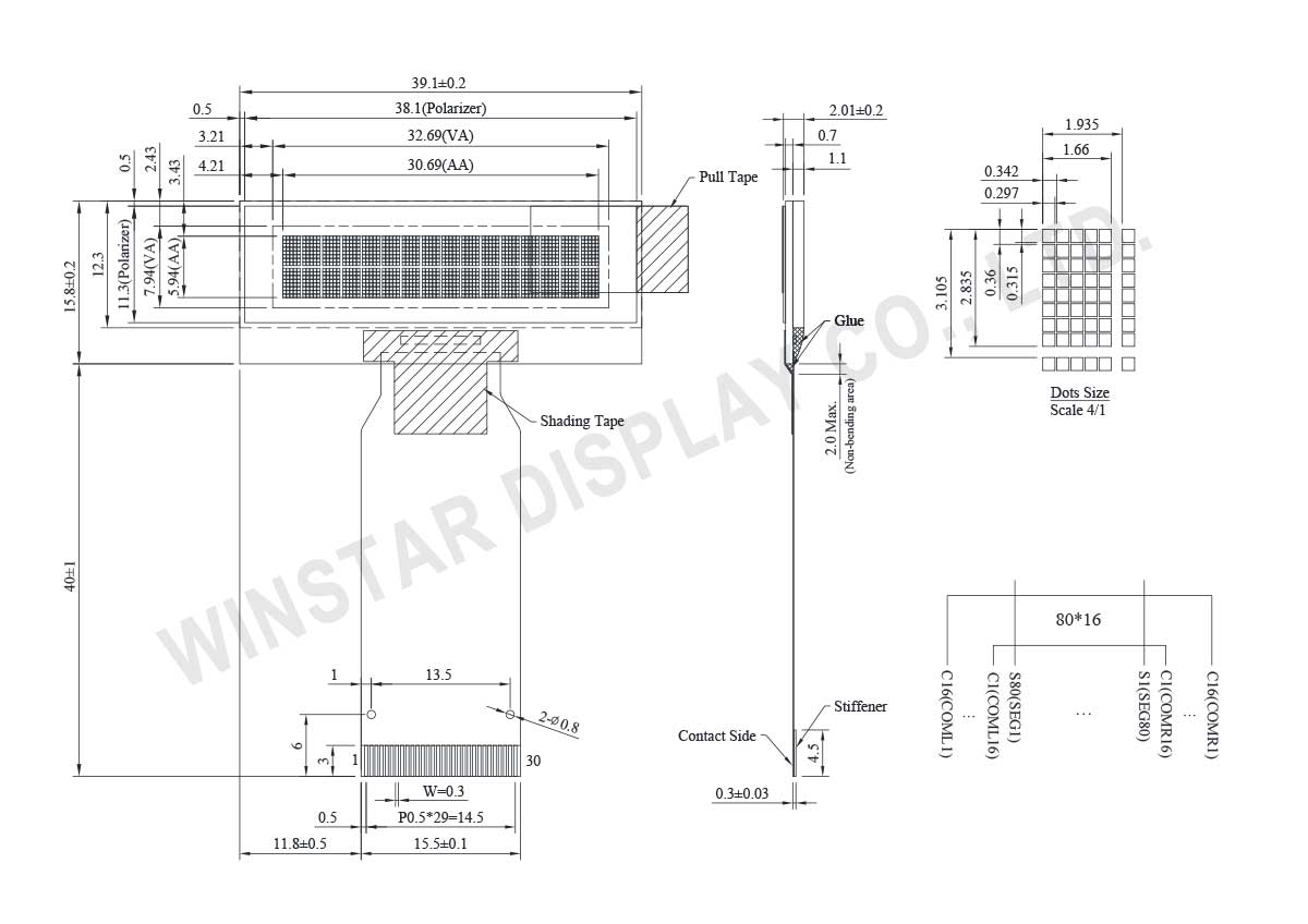
WEO001602Hは16文字 x 2行 COG構造のキャラクター有機ELディスプレイです。WS0012 ICを内蔵し、6800/8080 8ビット パラレルとI2C、 4線式のSPIインターフェイスをサポート致します。ロジックの電源電圧は3.3V (VDD) で、ディスプレイの電源電圧は8.5V(VCC) で、50%チェックボード電流での表示は2mA @ VCC 8.5V (白色の発光色)で、駆動デューティは1/16です。操作温度範囲は-40℃~ +80℃で、保存温度範囲は-40℃~ +85℃です。
この低消費電力の16x2キャラクター有機ELを使用し、既存のSTNキャラクターディスプレイを切り替えることをお勧めします。以下はこの有機ELディスプレイのメリットです。
►高速応答" +25 ℃で10 μ秒"
►広視野角"175度まで"
►薄い–バックライト不要、自発光
►高輝度
►高コントラスト"10,000:1
►広い操作温度範囲
►低消費電力

| 項目 | サイズ | 単位 |
|---|---|---|
| 表示形式 | 16 文字 x 2行 | - |
| モジュールサイズ | 39.1 x 15.8 x 2.01 | mm |
| 表示エリア | 32.69 x 7.94 | mm |
| アクティブエリア | 30.69 x 5.94 | mm |
| ドットサイズ | 0.297 x 0.315 | mm |
| ドットピッチ | 0.342 x 0.36 | mm |
| 文字サイズ | 1.66 x 2.835 | mm |
| 文字ピッチ | 1.935 x 3.105 | mm |
| パネルタイプ | OLED , モノクロ | |
| Duty | 1/16 | |
| IC | WS0012 | |
| インターフェイス | 6800, 8080, SPI, I2C | |
| 表示サイズ | 1.23 インチ | |
| 项目 | 符号 | 最小值 | 最大值 | 单位 |
|---|---|---|---|---|
| 操作温度 | TOP | -40 | +80 | °C |
| 保存温度 | TST | -40 | +85 | °C |
| ロジック電源電圧 | VCC | -0.3 | 3.6 | V |
| DCDC converter電源電圧 | VCI | -0.3 | 3.6 | V |
| Display電源電圧 | V16 | -0.3 | 19.0 | V |
| 項目 | 記号 | 条件 | 最小値 | 典型値 | 最大値 | 単位 |
|---|---|---|---|---|---|---|
| ロジック電源電圧 | VCC | - | 2.6 | 3.3 | 3.5 | V |
| DCDC converter電源電圧 | VCI | - | 2.6 | 3.3 | 3.5 | V |
| Display電源電圧 | V16 | - | - | 12.5 | 13.0 | V |
| 高レベル入力電圧 | VIH | - | 0.9xVCC | - | VCC | V |
| 低レベル入力電圧 | VIL | - | GND | - | 0.1xVCC | V |
| 高レベル出力電圧 | VOH | IOH=-0.5mA | 0.8xVCC | - | VCC | V |
| 低レベル出力電圧 | VOL | IOL=0.5mA | GND | - | 0.2xVCC | V |
| 50% Check Board Operating Current | I16 | V16=12.5V | - | 2 | 4 | mA |
| Pin No. | 記号 | Pin タイプ | 説明 | |||||||||||||||
|---|---|---|---|---|---|---|---|---|---|---|---|---|---|---|---|---|---|---|
| 1 | GND | P | Ground Pin | |||||||||||||||
| 2 | V16 | I | This is the most positive voltage supply pin of the chip. It can be supplied externally or generated internally by using internal DC-DC voltage converter. | |||||||||||||||
| 3 | VCI | P | DCDC buffer Power Supply | |||||||||||||||
| 4 | GND | P | Ground Pin | |||||||||||||||
| 5 | VCC | P | Power Pin | |||||||||||||||
| 6 | BVR | I | Brightness control pin. It should be connected to VCC. | |||||||||||||||
| 7 | DVR | I | Pre charge time control. It should be connected to VCC. | |||||||||||||||
| 8 | VBREF | O | This pin is the internal voltage reference of DCDC1 circuit. A stabilization capacitor should be connected between this pin and GND | |||||||||||||||
| 9 | RESE | I | NMOS source input pin: This pin connects to the source current pin of the external NMOS of the booster circuit. |
|||||||||||||||
| 10 | GDR | O | Gate drive pulse output pin: This output pin drives the gate of external NMOS of the booster circuit. |
|||||||||||||||
| 11 | FB | I | Feedback voltage input pin: This pin is the feedback resistor input of the booster circuit. It is used to adjust the booster output voltage level. |
|||||||||||||||
| 12 | VDD | P | Power Pin (connect to stabilization capacitor) | |||||||||||||||
| 13 | IM1 | I | Interface selection
|
|||||||||||||||
| 14 | IM0 | I | ||||||||||||||||
| 15 | RESETB | I | Reset pin | |||||||||||||||
| 16 | RS | I | Register Select Input Pin When this pin is set to "0", it is used as an Instruction Register. When this pin is set to "1", it is used for as the Data Register. |
|||||||||||||||
| 17 | CSB | I | Chip select input pins Data / instruction I/O is enabled only when CSB is “L”. |
|||||||||||||||
| 18 | RDB | I | Read / Write execution control pin
|
|||||||||||||||
| 19 | WRB | I | Read / Write execution control pin
|
|||||||||||||||
| 20 | SDA | I/O | SDA is the serial data input for I2C. | |||||||||||||||
| 21 | SDC | I/O | SDC is the serial clock input/output for I2C. | |||||||||||||||
| 22~25 | DB7~DB4 | I/O | High Order Bidirectional Data I/O Pins These pins are used for data transfer and reception between the MPU and WS0012. When SPI is selected, DB5 will be the serial clock input: SCL DB7 will be the serial data input: SDI. DB6 will be the serial data output: SDO. |
|||||||||||||||
| 26~29 | DB3~DB0 | I/O | Low Order Bidirectional Data I/O Pins These pins are used for data transfer and reception between the MPU and WS0012. These pins are not used during a 4-bit operation. |
|||||||||||||||
| 30 | GND | P | Ground Pin |
「すべてのクッキーを許可」をクリックすると、サイトのナビゲーションを向上させ、サイト使用状況を分析し、マーケティングおよびパフォーマンスの取り組みを支援するために、クッキーをデバイスに保存することに同意したことになります。この件に関する詳細情報は、ポリシーをご覧ください。プライバシーポリシー