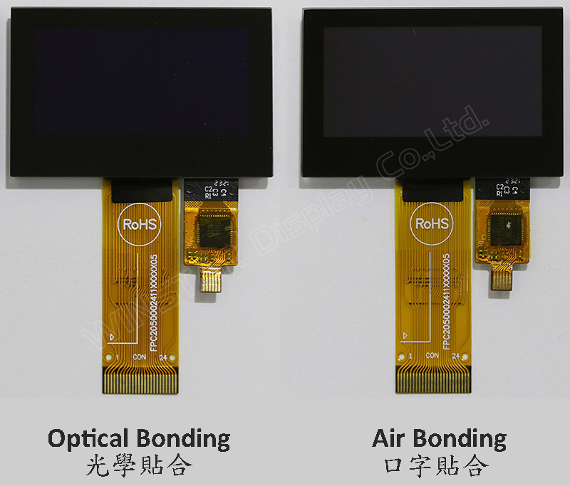
Il modello WEO012864A-CTP è un display OLED grafico COG da 1,54 pollici con pannello tattile capacitivo sul modulo, con una risoluzione di 128x64 pixel. Questo modulo è integrato con IC SSD1309; può essere comunicato tramite l'interfaccia parallela a 8 bit 6800/8080, SPI a 4 fili e I2C; la tensione di alimentazione per la logica va da 2,8V a 3,3V, valore tipico 3,0V, la tensione di alimentazione per il display è 12,5V, duty di guida 1/64. Forniamo due opzioni CTP per questo modello WEO012864A-CTP; un pannello touch CTP è tramite processo di Air Bonding, e l'altra opzione CTP è tramite processo di Optical Bonding (OCA). Entrambe le opzioni del pannello touch CTP sono integrate con IC FT6336U e supportano l'interfaccia I2C con un punto di rilevamento.
WEO012864A con il modello CTP è ideale per applicazioni smart home, dispositivi di tecnologia intelligente, dispositivi di misurazione, sistemi di controllo industriale, strumenti medici, ecc. Questo modulo può funzionare a temperature da -10℃ a +60℃; il suo intervallo di temperature di conservazione va da -20℃ a +70℃.
Il modulo OLED del modello WEO012864A-CTP presenta un alto rapporto di contrasto di 10.000:1, consentendo neri più vivaci e profondi e bianchi più luminosi. Ciò si traduce in un miglioramento della qualità dell'immagine, dettagli più nitidi e una migliore leggibilità.
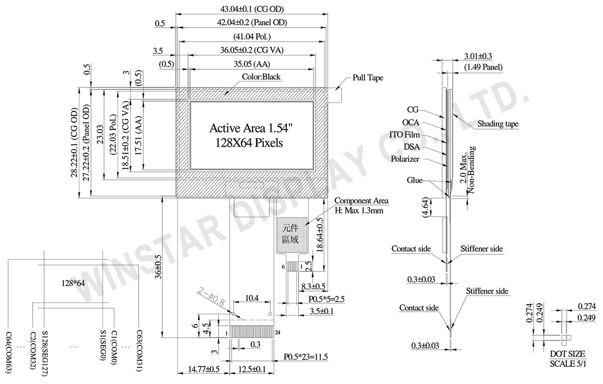
DISEGNO
Data source ref: WEO012864AWPP3D00001
SPECIFICHE TECNICHE
Dati meccanici
Articolo
Dimensioni
Unità
A matrice di punti
128 x 64
-
Dimensione del modulo
43.04 × 28.22 × 3.01
mm
Area attiva
35.05 × 17.51
mm
Dimensioni del Dot
0.249 × 0.249
mm
Passo del Dot
0.274 × 0.274
mm
Modalità display
Matrice passiva
Colore display
monocromatici
Drive Duty
1/64 Duty
IC
SSD1309
Interfaccia
6800,8080,4-wire SPI,I2C
Dimensione (Diagonale)
1.54 pollici
CTP IC
FT6336U
Punti di tocco
1
CTP Interfaccia
I2C
Superficie
Bagliore (Glare)
Valori massimi assoluti
Parameter
Simbolo
Valore Min
Valore massimo
Unità
Supply Voltage for Logic
VDD
-0.3
4
V
Supply Voltage for Display
VCC
0
17
V
Temperatura di lavoro
TOP
-10
+60
°C
Temperatura di stock
TSTG
-20
+70
°C
Touch Panel Controller FT6336U
Parameter
Simbolo
Valore Min
Valore massimo
Unità
Power Supply Voltage
VDD
0
3.6
V
Caratteristiche elettriche
DC Caratteristiche elettriche
Articolo
Simbolo
Condizione
Valore Min
Valore tipico
Valore massimo
Unità
Supply Voltage for Logic
VDD
-
2.8
3.0
3.3
V
Supply Voltage for Display
VCC
-
7.0
12.5
13.0
V
High Level Input
VIH
-
0.8×VDD
-
-
V
Low Level Input
VIL
-
-
-
0.2×VDD
V
High Level Output
VOH
-
0.9×VDD
-
-
V
Low Level Output
VOL
-
-
-
0.1×VDD
V
50% Check Board operating Current
VCC =12.5V
-
15
30
mA
Touch Panel Controller FT6336U
Articolo
Simbolo
Condizione
Valore Min
Valore tipico
Valore massimo
Unità
Supply Voltage
VDD
-
2.8
3.0
3.3
V
Input High Volt.
VIH
-
0.7×VDD
-
VDD
V
Input Low Volt.
VIL
-
-0.3
-
0.3×VDD
V
Output High Volt.
VOH
-
0.7×VDD
-
-
V
Output Low Volt.
VOL
-
-
-
0.3×VDD
V
Immagine
Modello numero
OLED IC
OLED Interfaccia
TP IC
TP Interfaccia
TP Punti di tocco
TP bonding method
WEO012864AWPP3A00000
SSD1309
6800,8080,4-wire SPI,I2C
FT6336U
I2C
1
OCA Optical-Bonding
WEO012864AWPP3D00001
SSD1309
6800,8080,4-wire SPI,I2C
FT6336U
I2C
1
Air-Bonding
Funzione dei Pin di Interfaccia
No.
Simbolo
Funzione
1
NC(GND)
No connection
2
VLSS
This is an analog ground pin
3
VSS
Ground.
4
NC
No connection
5
VDD
Power supply pin for core logic operation
6
BS1
MCU bus interface selection pins. Select appropriate logic setting as described in the following table. BS2 and BS1 are pin select
BS1
BS2
I2C
1
0
4-wire Serial
0
0
8-bit 68XX Parallel
0
1
8-bit 80XX Parallel
1
1
Note
(1) 0 is connected to VSS
(2) 1 is connected to VDD
7
BS2
8
CS#
This pin is the chip select input connecting to the MCU.
The chip is enabled for MCU communication only when CS# is pulled LOW (active LOW).
9
RES#
This pin is reset signal input.
When the pin is pulled LOW, initialization of the chip is executed.
Keep this pin pull HIGH during normal operation.
10
D/C#
This pin is Data/Command control pin connecting to the MCU.
When the pin is pulled HIGH, the data at D[7:0] will be interpreted as data.
When the pin is pulled LOW, the data at D[7:0] will be transferred to a command register.
In I2C mode, this pin acts as SA0 for slave address selection.
11
R/W#
This pin is read / write control input pin connecting to the MCU interface.
When 6800 interface mode is selected, this pin will be used as Read/Write (R/W#) selection input. Read mode will be carried out when this pin is pulled HIGH and write mode when LOW.
When 8080 interface mode is selected, this pin will be the Write (WR#) input. Data write operation is initiated when this pin is pulled LOW and the chip is selected.
When serial or I2C interface is selected, this pin must be connected to VSS.
12
E/RD#
This pin is MCU interface input.
When 6800 interface mode is selected, this pin will be used as the Enable (E) signal.
Read/write operation is initiated when this pin is pulled HIGH and the chip is selected.
When 8080 interface mode is selected, this pin receives the Read (RD#) signal. Read operation is initiated when this pin is pulled LOW and the chip is selected.
When serial or I2C interface is selected, this pin must be connected to VSS.
13-20
D0~D7
These pins are bi-directional data bus connecting to the MCU data bus.
Unused pins are recommended to tie LOW.
When serial interface mode is selected, D0 will be the serial clock input: SCLK; D1 will be the serial data input: SDIN and D2 should be kept NC.
When I2C mode is selected, D2, D1 should be tied together and serve as SDAout, SDAin in application and D0 is the serial clock input, SCL.
21
IREF
This pin is the segment output current reference pin.
IREF is supplied externally.
22
VCOMH
COM signal deselected voltage level.
A capacitor should be connected between this pin and VSS.
23
VCC
Power supply for panel driving voltage. This is also the most positive power voltage supply pin.
Facendo clic su "Consenti tutti i cookie", accetti la memorizzazione dei cookie sul tuo dispositivo per migliorare la navigazione del sito, analizzare l'utilizzo del sito e assistere nei nostri sforzi di marketing e prestazioni. Puoi trovare ulteriori informazioni su questo argomento nella nostra politica. Informativa sulla privacy