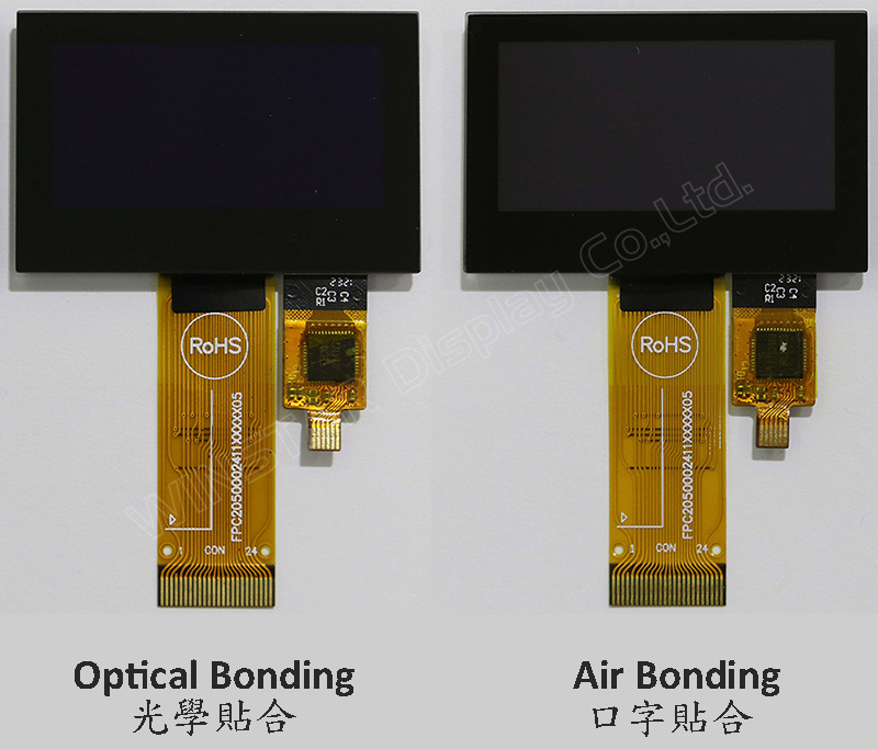
El modelo WEO012864A-CTP es una pantalla OLED gráfica COG de 1,54 pulgadas con panel táctil capacitivo en el módulo, con una resolución de 128x64 píxeles. Este módulo está integrado con el circuito integrado SSD1309; puede comunicarse a través de la interfaz paralela de 6800/8080 de 8 bits, la interfaz SPI de 4 cables y I2C; el voltaje de alimentación para la lógica es de 2,8V a 3,3V, con un valor típico de 3,0V, el voltaje de alimentación para la pantalla es de 12,5V, con un duty de conducción de 1/64. Ofrecemos dos opciones de CTP para este modelo WEO012864A-CTP; una opción de panel táctil CTP es a través del proceso de unión por aire, y la otra opción de CTP es a través del proceso de unión óptica (OCA). Ambas opciones de panel táctil CTP están integradas con el circuito FT6336U IC y admiten la interfaz I2C con un punto de detección.
WEO012864A con el modelo CTP es ideal para aplicaciones de hogares inteligentes, dispositivos de tecnología inteligente, dispositivos de medición, sistemas de control industrial, instrumentos médicos, etc. Este módulo puede funcionar a temperaturas de -10℃ a +60℃; su rango de temperaturas de almacenamiento va desde -20℃ a +70℃.
El módulo OLED del modelo WEO012864A-CTP presenta una alta relación de contraste de 10000:1, lo que permite negros más vibrantes y profundos, y blancos más brillantes. Esto resulta en una mejora en la calidad de la imagen, detalles más nítidos y una mejor legibilidad.
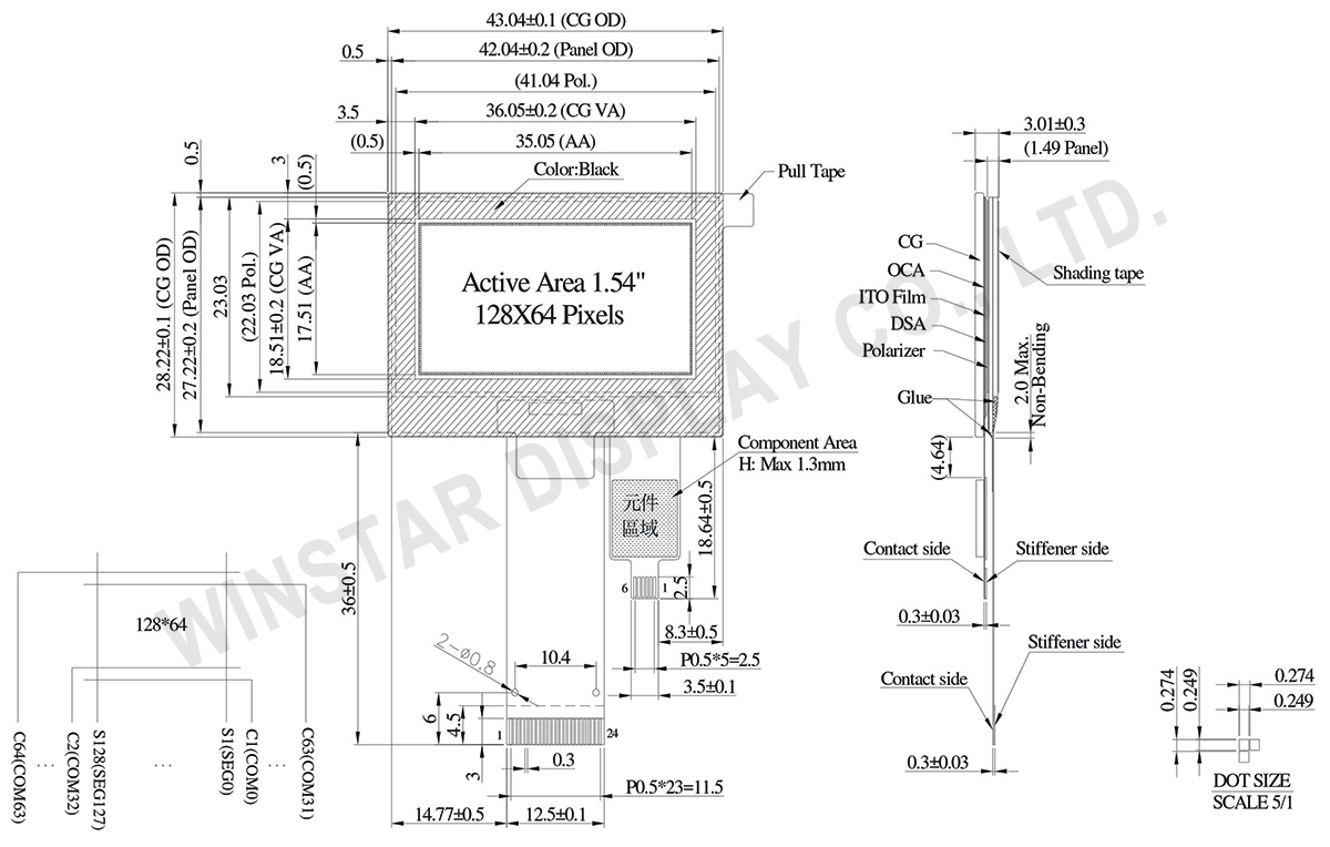
DIBUJO
Data source ref: WEO012864AWPP3D00001
ESPECIFICACIONES
Datos mecánicos
Elemento
Dimensión
Unidad
Matriz de puntos
128 x 64
-
Dimensión del módulo
43.04 × 28.22 × 3.01
mm
zona activa
35.05 × 17.51
mm
Tamaño del punto
0.249 × 0.249
mm
Distancia entre puntos
0.274 × 0.274
mm
Modo de visualización
Matriz pasiva
Color de la pantalla
Monocromos
Drive Duty
1/64 Duty
IC
SSD1309
Interfaz
6800,8080,4-wire SPI,I2C
Tamaño (Diagonal)
1.54 pulgada
CTP IC
FT6336U
Puntos táctiles
1
CTP Interfaz
I2C
Superficie
Deslumbramiento
Valores nominales máximos absolutos
Parameter
Símbolo
Valor mín.
Valor máx.
Unidad
Supply Voltage for Logic
VDD
-0.3
4
V
Supply Voltage for Display
VCC
0
17
V
Temperatura de funcionamiento
TOP
-10
+60
°C
Temperatura de almacenamiento
TSTG
-20
+70
°C
Touch Panel Controller FT6336U
Parameter
Símbolo
Valor mín.
Valor máx.
Unidad
Power Supply Voltage
VDD
0
3.6
V
Características electrónicas
DC Características electrónicas
Elemento
Símbolo
Condición
Valor mín.
Valor típico
Valor máx.
Unidad
Supply Voltage for Logic
VDD
-
2.8
3.0
3.3
V
Supply Voltage for Display
VCC
-
7.0
12.5
13.0
V
High Level Input
VIH
-
0.8×VDD
-
-
V
Low Level Input
VIL
-
-
-
0.2×VDD
V
High Level Output
VOH
-
0.9×VDD
-
-
V
Low Level Output
VOL
-
-
-
0.1×VDD
V
50% Check Board operating Current
VCC =12.5V
-
15
30
mA
Touch Panel Controller FT6336U
Elemento
Símbolo
Condición
Valor mín.
Valor típico
Valor máx.
Unidad
Supply Voltage
VDD
-
2.8
3.0
3.3
V
Input High Volt.
VIH
-
0.7×VDD
-
VDD
V
Input Low Volt.
VIL
-
-0.3
-
0.3×VDD
V
Output High Volt.
VOH
-
0.7×VDD
-
-
V
Output Low Volt.
VOL
-
-
-
0.3×VDD
V
Imagen
Modelo Nº
OLED IC
OLED Interfaz
TP IC
TP Interfaz
TP Puntos táctiles
TP bonding method
WEO012864AWPP3A00000
SSD1309
6800,8080,4-wire SPI,I2C
FT6336U
I2C
1
OCA Optical-Bonding
WEO012864AWPP3D00001
SSD1309
6800,8080,4-wire SPI,I2C
FT6336U
I2C
1
Air-Bonding
Función interfaz Pin
No.
Símbolo
Función
1
NC(GND)
No connection
2
VLSS
This is an analog ground pin
3
VSS
Ground.
4
NC
No connection
5
VDD
Power supply pin for core logic operation
6
BS1
MCU bus interface selection pins. Select appropriate logic setting as described in the following table. BS2 and BS1 are pin select
BS1
BS2
I2C
1
0
4-wire Serial
0
0
8-bit 68XX Parallel
0
1
8-bit 80XX Parallel
1
1
Note
(1) 0 is connected to VSS
(2) 1 is connected to VDD
7
BS2
8
CS#
This pin is the chip select input connecting to the MCU.
The chip is enabled for MCU communication only when CS# is pulled LOW (active LOW).
9
RES#
This pin is reset signal input.
When the pin is pulled LOW, initialization of the chip is executed.
Keep this pin pull HIGH during normal operation.
10
D/C#
This pin is Data/Command control pin connecting to the MCU.
When the pin is pulled HIGH, the data at D[7:0] will be interpreted as data.
When the pin is pulled LOW, the data at D[7:0] will be transferred to a command register.
In I2C mode, this pin acts as SA0 for slave address selection.
11
R/W#
This pin is read / write control input pin connecting to the MCU interface.
When 6800 interface mode is selected, this pin will be used as Read/Write (R/W#) selection input. Read mode will be carried out when this pin is pulled HIGH and write mode when LOW.
When 8080 interface mode is selected, this pin will be the Write (WR#) input. Data write operation is initiated when this pin is pulled LOW and the chip is selected.
When serial or I2C interface is selected, this pin must be connected to VSS.
12
E/RD#
This pin is MCU interface input.
When 6800 interface mode is selected, this pin will be used as the Enable (E) signal.
Read/write operation is initiated when this pin is pulled HIGH and the chip is selected.
When 8080 interface mode is selected, this pin receives the Read (RD#) signal. Read operation is initiated when this pin is pulled LOW and the chip is selected.
When serial or I2C interface is selected, this pin must be connected to VSS.
13-20
D0~D7
These pins are bi-directional data bus connecting to the MCU data bus.
Unused pins are recommended to tie LOW.
When serial interface mode is selected, D0 will be the serial clock input: SCLK; D1 will be the serial data input: SDIN and D2 should be kept NC.
When I2C mode is selected, D2, D1 should be tied together and serve as SDAout, SDAin in application and D0 is the serial clock input, SCL.
21
IREF
This pin is the segment output current reference pin.
IREF is supplied externally.
22
VCOMH
COM signal deselected voltage level.
A capacitor should be connected between this pin and VSS.
23
VCC
Power supply for panel driving voltage. This is also the most positive power voltage supply pin.
Al hacer clic en "Permitir todas las cookies", aceptas el almacenamiento de cookies en tu dispositivo para mejorar la navegación en el sitio, analizar el uso del sitio y ayudar en nuestros esfuerzos de marketing y rendimiento. Puedes encontrar más información sobre este tema en nuestra política. Política de privacidad