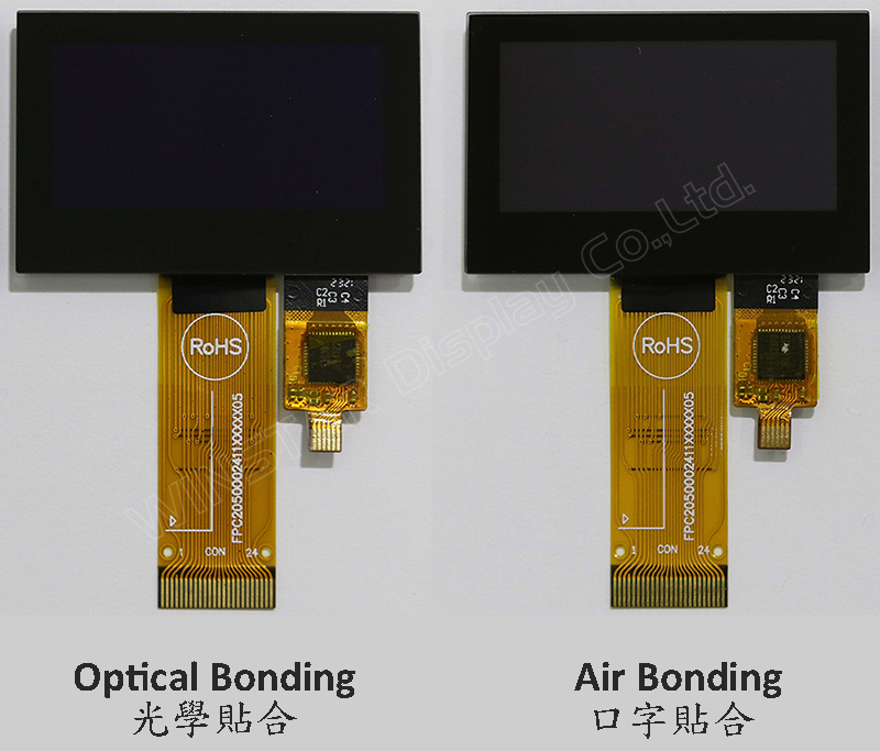
Das Modell WEO012864A-CTP ist ein 1,54 Zoll COG-Struktur-Grafik-OLED-Display mit kapazitivem Touchpanel auf dem Modul, mit einer Auflösung von 128x64 Pixeln. Dieses Modul ist mit dem SSD1309-IC ausgestattet; es kann über die 6800/8080 8-Bit-Parallel-, 4-Draht-SPI- und I2C-Schnittstelle kommunizieren; die Versorgungsspannung für die Logik beträgt 2,8V bis 3,3V, der typische Wert beträgt 3,0V, die Versorgungsspannung für das Display beträgt 12,5V, 1/64 Ansteuerungsduty. Wir bieten zwei CTP-Optionen für dieses WEO012864A-CTP-Modell an; eine CTP-Touch-Panel-Option erfolgt über den Air Bonding-Prozess, die andere CTP-Option erfolgt über den Optical Bonding (OCA)-Prozess. Diese beiden CTP-Touchpanel-Optionen sind beide mit dem FT6336U-IC integriert und unterstützen die I2C-Schnittstelle mit einem Erkennungspunkt.
WEO012864A mit dem CTP-Modell eignet sich ideal für Smart-Home-Anwendungen, intelligente Technologiegeräte, Messgeräte, industrielle Steuerungssysteme, medizinische Instrumente usw. Dieses Modul kann bei Temperaturen von -10℃ bis +60℃ betrieben werden; sein Temperaturbereich für die Lagerung reicht von -20℃ bis +70℃.
Das OLED-Modul des WEO012864A-CTP-Modells bietet ein hohes Kontrastverhältnis von 10.000:1, was lebendigere und tiefere Schwarztöne sowie hellere Weißtöne ermöglicht. Dies führt zu einer verbesserten Bildqualität, schärferen Details und verbesserter Lesbarkeit.
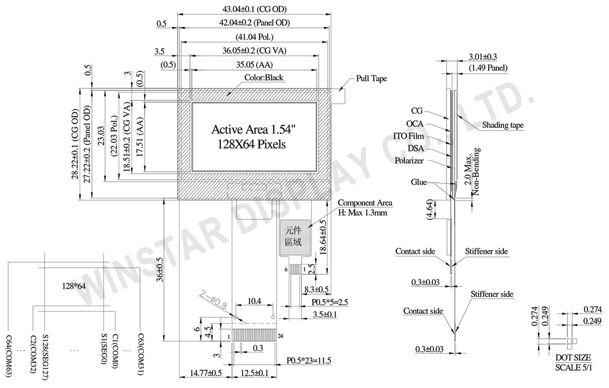
Zeichnung
Data source ref: WEO012864AWPP3D00001
Technische Daten
mechanische Daten
Artikel
Ausmaß
Einheit
Punktmatrix
128 x 64
-
Abmaße der modul
43,04 × 28,22 × 3,01
mm
Aktiver Bereich
35,05 × 17,51
mm
Punktgröße
0,249 × 0,249
mm
Punktabstand
0,274 × 0,274
mm
Display Mode
Passive Matrix
Display Color
Moncohromes
Drive Duty
1/64 Duty
IC
SSD1309
Schnittstelle
6800,8080,4-wire SPI,I2C
Größe (Diagonale)
1,54 Zoll
CTP IC
FT6336U
Berührungspunkte
1
CTP Schnittstelle
I2C
Oberfläche
Glanz
Absolute Grenzwerte
Parameter
Symbol
Mindestwert
Maximalwert
Einheit
Supply Voltage for Logic
VDD
-0,3
4
V
Supply Voltage for Display
VCC
0
17
V
Betriebstemperatur
TOP
-10
+60
°C
Lagertemperatur
TSTG
-20
+70
°C
Touch Panel Controller FT6336U
Parameter
Symbol
Mindestwert
Maximalwert
Einheit
Power Supply Voltage
VDD
0
3,6
V
elektronische Eingenschaften
DC elektronische Eingenschaften
Artikel
Symbol
Bedingung
Mindestwert
typischer Wert
Maximalwert
Einheit
Supply Voltage for Logic
VDD
-
2,8
3,0
3,3
V
Supply Voltage for Display
VCC
-
7,0
12,5
13,0
V
High Level Input
VIH
-
0,8×VDD
-
-
V
Low Level Input
VIL
-
-
-
0,2×VDD
V
High Level Output
VOH
-
0,9×VDD
-
-
V
Low Level Output
VOL
-
-
-
0,1×VDD
V
50% Check Board operating Current
VCC =12,5V
-
15
30
mA
Touch Panel Controller FT6336U
Artikel
Symbol
Bedingung
Mindestwert
typischer Wert
Maximalwert
Einheit
Supply Voltage
VDD
-
2,8
3,0
3,3
V
Input High Volt.
VIH
-
0,7×VDD
-
VDD
V
Input Low Volt.
VIL
-
-0,3
-
0,3×VDD
V
Output High Volt.
VOH
-
0,7×VDD
-
-
V
Output Low Volt.
VOL
-
-
-
0,3×VDD
V
Bild
Modellnummer
OLED IC
OLED Schnittstelle
TP IC
TP Schnittstelle
TP Berührungspunkte
TP bonding method
WEO012864AWPP3A00000
SSD1309
6800,8080,4-wire SPI,I2C
FT6336U
I2C
1
OCA Optical-Bonding
WEO012864AWPP3D00001
SSD1309
6800,8080,4-wire SPI,I2C
FT6336U
I2C
1
Air-Bonding
Schnittstelle Pin-Funktion
No.
Symbol
Beschreibung
1
NC(GND)
No connection
2
VLSS
This is an analog ground pin
3
VSS
Ground.
4
NC
No connection
5
VDD
Power supply pin for core logic operation
6
BS1
MCU bus interface selection pins. Select appropriate logic setting as described in the following table. BS2 and BS1 are pin select
BS1
BS2
I2C
1
0
4-wire Serial
0
0
8-bit 68XX Parallel
0
1
8-bit 80XX Parallel
1
1
Note
(1) 0 is connected to VSS
(2) 1 is connected to VDD
7
BS2
8
CS#
This pin is the chip select input connecting to the MCU.
The chip is enabled for MCU communication only when CS# is pulled LOW (active LOW).
9
RES#
This pin is reset signal input.
When the pin is pulled LOW, initialization of the chip is executed.
Keep this pin pull HIGH during normal operation.
10
D/C#
This pin is Data/Command control pin connecting to the MCU.
When the pin is pulled HIGH, the data at D[7:0] will be interpreted as data.
When the pin is pulled LOW, the data at D[7:0] will be transferred to a command register.
In I2C mode, this pin acts as SA0 for slave address selection.
11
R/W#
This pin is read / write control input pin connecting to the MCU interface.
When 6800 interface mode is selected, this pin will be used as Read/Write (R/W#) selection input. Read mode will be carried out when this pin is pulled HIGH and write mode when LOW.
When 8080 interface mode is selected, this pin will be the Write (WR#) input. Data write operation is initiated when this pin is pulled LOW and the chip is selected.
When serial or I2C interface is selected, this pin must be connected to VSS.
12
E/RD#
This pin is MCU interface input.
When 6800 interface mode is selected, this pin will be used as the Enable (E) signal.
Read/write operation is initiated when this pin is pulled HIGH and the chip is selected.
When 8080 interface mode is selected, this pin receives the Read (RD#) signal. Read operation is initiated when this pin is pulled LOW and the chip is selected.
When serial or I2C interface is selected, this pin must be connected to VSS.
13-20
D0~D7
These pins are bi-directional data bus connecting to the MCU data bus.
Unused pins are recommended to tie LOW.
When serial interface mode is selected, D0 will be the serial clock input: SCLK; D1 will be the serial data input: SDIN and D2 should be kept NC.
When I2C mode is selected, D2, D1 should be tied together and serve as SDAout, SDAin in application and D0 is the serial clock input, SCL.
21
IREF
This pin is the segment output current reference pin.
IREF is supplied externally.
22
VCOMH
COM signal deselected voltage level.
A capacitor should be connected between this pin and VSS.
23
VCC
Power supply for panel driving voltage. This is also the most positive power voltage supply pin.
Durch Klicken auf „Alle Cookies zulassen“ stimmen Sie der Speicherung von Cookies auf Ihrem Gerät zu, um die Navigation auf der Website zu verbessern, die Nutzung der Website zu analysieren und unsere Marketing- und Leistungsbemühungen zu unterstützen. Weitere Informationen zu diesem Thema finden Sie in unserer Richtlinie. Datenschutzrichtlinie