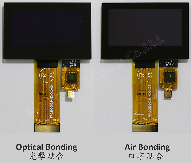
O modelo WEO012864A-CTP é um display OLED gráfico COG de 1,54 polegadas com Painel de Toque Capacitivo no módulo, com resolução de 128x64 pixels. Este módulo é incorporado com o circuito integrado SSD1309; pode ser comunicado através da interface paralela de 6800/8080 de 8 bits, interface SPI de 4 fios e I2C; a tensão de alimentação para lógica é de 2,8V a 3,3V, valor típico de 3,0V, a tensão de alimentação para o display é de 12,5V, duty de condução 1/64. Fornecemos duas opções de CTP para este modelo WEO012864A-CTP; um painel de toque CTP é por processo de Air Bonding, e a outra opção de CTP é por processo de Optical Bonding (OCA). Ambas as opções de painel de toque CTP são incorporadas com o circuito FT6336U IC e suportam a interface I2C com um ponto de detecção.
WEO012864A com o modelo CTP é ideal para aplicações de casas inteligentes, dispositivos de tecnologia inteligente, dispositivos de medição, sistemas de controle industrial, instrumentos médicos, etc. Este módulo pode operar em temperaturas de -10℃ a +60℃; sua faixa de temperaturas de armazenamento varia de -20℃ a +70℃.
O módulo OLED do modelo WEO012864A-CTP apresenta uma alta relação de contraste de 10.000:1, permitindo pretos mais vibrantes e profundos e brancos mais brilhantes. Isso resulta em uma melhoria na qualidade da imagem, detalhes mais nítidos e melhor legibilidade.
DRAWING
Data source ref: WEO012864AWPP3D00001
SPECIFICATIONS
Dados Mecânicos
Item
Dimensão
Unidade
Matriz de pontos
128 x 64
-
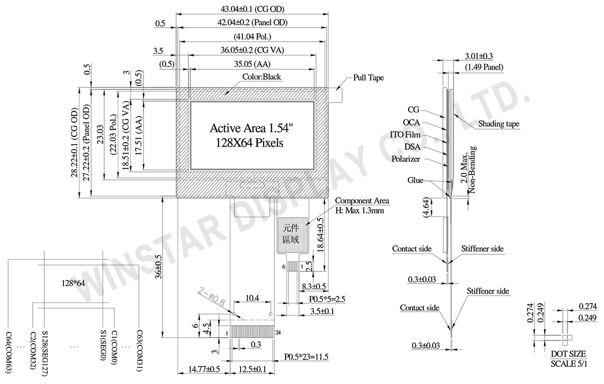
Dimensão do módulo
43.04 × 28.22 × 3.01
mm
Área ativa
35.05 × 17.51
mm
Tamanho do ponto
0.249 × 0.249
mm
Distância entre pontos
0.274 × 0.274
mm
Modo de exibição
Passive Matrix
Cor de exibição
Monochrome
Drive Duty
1/64 Duty
IC
SSD1309
Interface
6800,8080,4-wire SPI,I2C
Tamanho
1,54 polegadas
CTP IC
FT6336U
Detect Point
1
CTP Interface
I2C
Superfície
Reflexo
Classificações Máximas Absolutas
Parameter
Símbolo
Valor Min
Valor Máximo
Unidade
Supply Voltage for Logic
VDD
-0.3
4
V
Supply Voltage for Display
VCC
0
17
V
Temperatura de operação
TOP
-10
+60
°C
Temperatura de armazenamento
TSTG
-20
+70
°C
Touch Panel Controller FT6336U
Parameter
Símbolo
Valor Min
Valor Máximo
Unidade
Power Supply Voltage
VDD
0
3.6
V
Características Eletrônicas
DC Características Eletrônicas
Item
Símbolo
Condition
Valor Min
Valor Típico
Valor Máximo
Unidade
Supply Voltage for Logic
VDD
-
2.8
3.0
3.3
V
Supply Voltage for Display
VCC
-
7.0
12.5
13.0
V
High Level Input
VIH
-
0.8×VDD
-
-
V
Low Level Input
VIL
-
-
-
0.2×VDD
V
High Level Output
VOH
-
0.9×VDD
-
-
V
Low Level Output
VOL
-
-
-
0.1×VDD
V
50% Check Board operating Current
VCC =12.5V
-
15
30
mA
Touch Panel Controller FT6336U
Item
Símbolo
Condition
Valor Min
Valor Típico
Valor Máximo
Unidade
Supply Voltage
VDD
-
2.8
3.0
3.3
V
Input High Volt.
VIH
-
0.7×VDD
-
VDD
V
Input Low Volt.
VIL
-
-0.3
-
0.3×VDD
V
Output High Volt.
VOH
-
0.7×VDD
-
-
V
Output Low Volt.
VOL
-
-
-
0.3×VDD
V
Imagem
Part Number
OLED IC
OLED Interface
TP IC
TP Interface
TP Detect Point
TP bonding method
WEO012864AWPP3A00000
SSD1309
6800,8080,4-wire SPI,I2C
FT6336U
I2C
1
OCA Optical-Bonding
WEO012864AWPP3D00001
SSD1309
6800,8080,4-wire SPI,I2C
FT6336U
I2C
1
Air-Bonding
Função do pino de interface
No.
Símbolo
Função
1
NC(GND)
No connection
2
VLSS
This is an analog ground pin
3
VSS
Ground.
4
NC
No connection
5
VDD
Power supply pin for core logic operation
6
BS1
MCU bus interface selection pins. Select appropriate logic setting as described in the following table. BS2 and BS1 are pin select
BS1
BS2
I2C
1
0
4-wire Serial
0
0
8-bit 68XX Parallel
0
1
8-bit 80XX Parallel
1
1
Note
(1) 0 is connected to VSS
(2) 1 is connected to VDD
7
BS2
8
CS#
This pin is the chip select input connecting to the MCU.
The chip is enabled for MCU communication only when CS# is pulled LOW (active LOW).
9
RES#
This pin is reset signal input.
When the pin is pulled LOW, initialization of the chip is executed.
Keep this pin pull HIGH during normal operation.
10
D/C#
This pin is Data/Command control pin connecting to the MCU.
When the pin is pulled HIGH, the data at D[7:0] will be interpreted as data.
When the pin is pulled LOW, the data at D[7:0] will be transferred to a command register.
In I2C mode, this pin acts as SA0 for slave address selection.
11
R/W#
This pin is read / write control input pin connecting to the MCU interface.
When 6800 interface mode is selected, this pin will be used as Read/Write (R/W#) selection input. Read mode will be carried out when this pin is pulled HIGH and write mode when LOW.
When 8080 interface mode is selected, this pin will be the Write (WR#) input. Data write operation is initiated when this pin is pulled LOW and the chip is selected.
When serial or I2C interface is selected, this pin must be connected to VSS.
12
E/RD#
This pin is MCU interface input.
When 6800 interface mode is selected, this pin will be used as the Enable (E) signal.
Read/write operation is initiated when this pin is pulled HIGH and the chip is selected.
When 8080 interface mode is selected, this pin receives the Read (RD#) signal. Read operation is initiated when this pin is pulled LOW and the chip is selected.
When serial or I2C interface is selected, this pin must be connected to VSS.
13-20
D0~D7
These pins are bi-directional data bus connecting to the MCU data bus.
Unused pins are recommended to tie LOW.
When serial interface mode is selected, D0 will be the serial clock input: SCLK; D1 will be the serial data input: SDIN and D2 should be kept NC.
When I2C mode is selected, D2, D1 should be tied together and serve as SDAout, SDAin in application and D0 is the serial clock input, SCL.
21
IREF
This pin is the segment output current reference pin.
IREF is supplied externally.
22
VCOMH
COM signal deselected voltage level.
A capacitor should be connected between this pin and VSS.
23
VCC
Power supply for panel driving voltage. This is also the most positive power voltage supply pin.
Ao clicar em "Permitir todos os cookies", você concorda com o armazenamento de cookies no seu dispositivo para melhorar a navegação no site, analisar o uso do site e auxiliar nossos esforços de marketing e desempenho. Você pode encontrar mais informações sobre esse assunto em nossa política. Política de privacidade

 - WEO012864A-CTP")
 - WEO012864A-CTP")
 - WEO012864A-CTP")
 - WEO012864A-CTP")
 - WEO012864A-CTP")
 - WEO012864A-CTP")
 - WEO012864A-CTP")