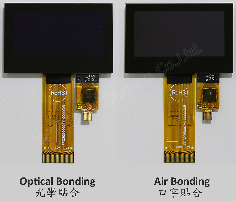
Model WEO012864A-CTP to 1,54-calowy wyświetlacz OLED typu COG z panelu dotykowego pojemnościowego na moduł, o rozdzielczości 128x64 pikseli. Ten moduł jest wyposażony w układ SSD1309 IC; może być komunikowany za pomocą interfejsu równoległego 6800/8080 8-bitowego, interfejsu SPI 4-przewodowego i I2C; napięcie zasilania dla logiki wynosi od 2,8V do 3,3V, wartość typowa 3,0V, napięcie zasilania dla wyświetlacza wynosi 12,5V, obowiązek 1/64. Dostarczamy dwie opcje CTP dla modelu WEO012864A-CTP; jeden panel dotykowy CTP jest przez proces Air Bonding, a druga opcja CTP jest przez proces Optical Bonding (OCA). Obie opcje panelu dotykowego CTP są wyposażone w układ FT6336U IC i obsługują interfejs I2C z jednym punktem wykrywania.
WEO012864A z modelem CTP jest idealny do zastosowań w inteligentnych domach, inteligentnych urządzeniach technologicznych, urządzeniach pomiarowych, systemach sterowania przemysłowego, przyrządach medycznych, itp. Ten moduł może działać w temperaturach od -10℃ do +60℃; jego zakres temperatur przechowywania wynosi od -20℃ do +70℃.
Moduł OLED modelu WEO012864A-CTP ma wysoki stosunek kontrastu 10 000:1, co pozwala na bardziej żywe i głębsze czernie oraz jaśniejsze biel. To prowadzi do poprawy jakości obrazu, ostrzejszych szczegółów i lepszej czytelności.
Rysunek
Data source ref: WEO012864AWPP3D00001
Specyfikacja
Dane mechaniczne
Rzecz
Wymiar
Jednostka
Matryca punktowa
128 x 64
-
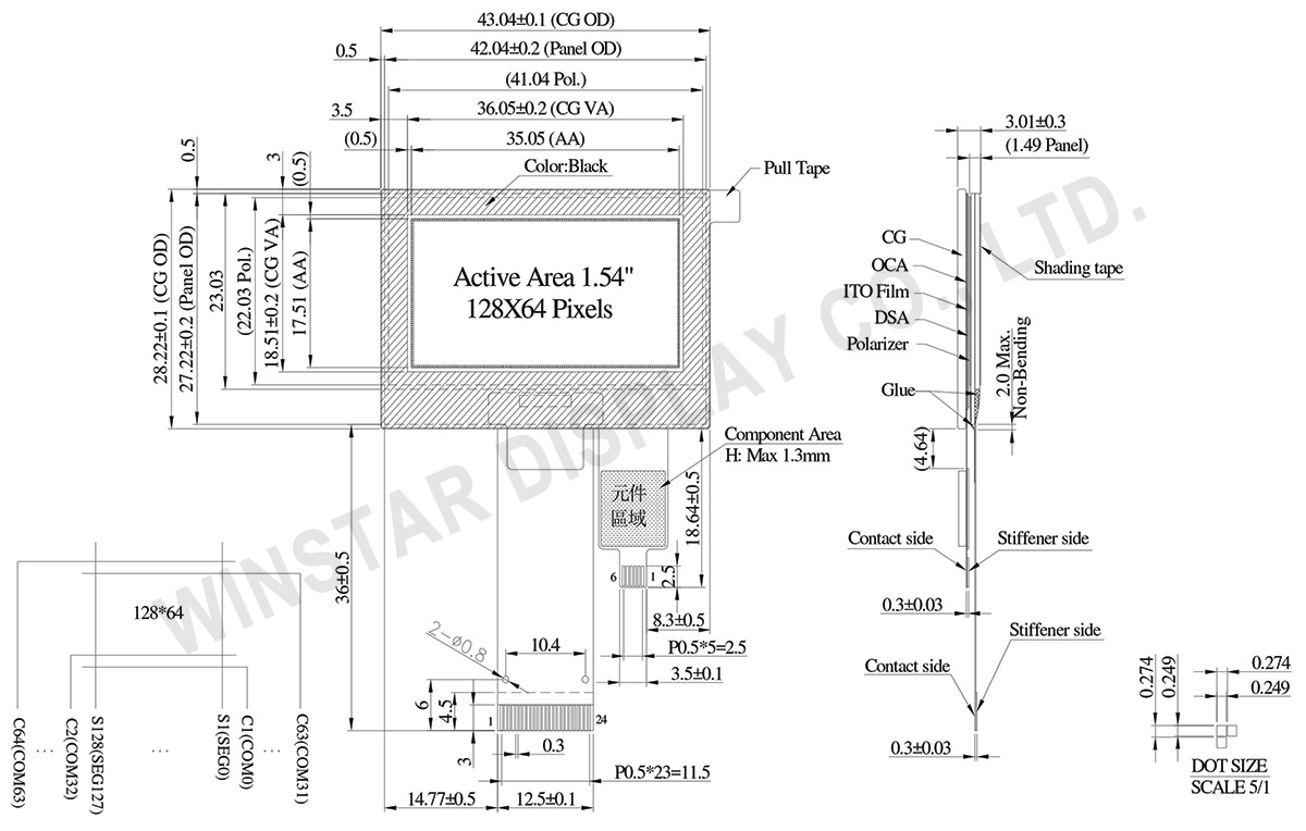
Wymiary modułu
43.04 × 28.22 × 3.01
mm
Obszar aktywny
35.05 × 17.51
mm
Wielkość piksela
0.249 × 0.249
mm
Raster pomiędzy pikselami
0.274 × 0.274
mm
Tryb wyświetlania
matryca
Kolor wyświetlacza
Monochromatyczny
Drive Duty
1/64 Duty
IC
SSD1309
Interfejs
6800,8080,4-wire SPI,I2C
Rozmiar (Przekątna)
1.54 cala
CTP IC
FT6336U
Punkty dotyku
1
CTP Interfejs
I2C
Powierzchnia
Normal Glare
Bezwzględne oceny maksymalne
Parameter
Symbol
Minimalna wartość
Maksymalna wartość
Jednostka
Supply Voltage for Logic
VDD
-0.3
4
V
Supply Voltage for Display
VCC
0
17
V
Temperatura pracy
TOP
-10
+60
°C
Temperatura przechowywania
TSTG
-20
+70
°C
Touch Panel Controller FT6336U
Parameter
Symbol
Minimalna wartość
Maksymalna wartość
Jednostka
Power Supply Voltage
VDD
0
3.6
V
Parametry elektryczne
DC Parametry elektryczne
Rzecz
Symbol
Stan
Minimalna wartość
Rodzaj działalności
Maksymalna wartość
Jednostka
Supply Voltage for Logic
VDD
-
2.8
3.0
3.3
V
Supply Voltage for Display
VCC
-
7.0
12.5
13.0
V
High Level Input
VIH
-
0.8×VDD
-
-
V
Low Level Input
VIL
-
-
-
0.2×VDD
V
High Level Output
VOH
-
0.9×VDD
-
-
V
Low Level Output
VOL
-
-
-
0.1×VDD
V
50% Check Board operating Current
VCC =12.5V
-
15
30
mA
Touch Panel Controller FT6336U
Rzecz
Symbol
Stan
Minimalna wartość
Rodzaj działalności
Maksymalna wartość
Jednostka
Supply Voltage
VDD
-
2.8
3.0
3.3
V
Input High Volt.
VIH
-
0.7×VDD
-
VDD
V
Input Low Volt.
VIL
-
-0.3
-
0.3×VDD
V
Output High Volt.
VOH
-
0.7×VDD
-
-
V
Output Low Volt.
VOL
-
-
-
0.3×VDD
V
Obraz
Numer modelu
OLED IC
OLED Interfejs
TP IC
TP Interfejs
TP Punkty dotyku
TP bonding method
WEO012864AWPP3A00000
SSD1309
6800,8080,4-wire SPI,I2C
FT6336U
I2C
1
OCA Optical-Bonding
WEO012864AWPP3D00001
SSD1309
6800,8080,4-wire SPI,I2C
FT6336U
I2C
1
Air-Bonding
Funkcja pinów interfejsu
No.
Symbol
Funkcja
1
NC(GND)
No connection
2
VLSS
This is an analog ground pin
3
VSS
Ground.
4
NC
No connection
5
VDD
Power supply pin for core logic operation
6
BS1
MCU bus interface selection pins. Select appropriate logic setting as described in the following table. BS2 and BS1 are pin select
BS1
BS2
I2C
1
0
4-wire Serial
0
0
8-bit 68XX Parallel
0
1
8-bit 80XX Parallel
1
1
Note
(1) 0 is connected to VSS
(2) 1 is connected to VDD
7
BS2
8
CS#
This pin is the chip select input connecting to the MCU.
The chip is enabled for MCU communication only when CS# is pulled LOW (active LOW).
9
RES#
This pin is reset signal input.
When the pin is pulled LOW, initialization of the chip is executed.
Keep this pin pull HIGH during normal operation.
10
D/C#
This pin is Data/Command control pin connecting to the MCU.
When the pin is pulled HIGH, the data at D[7:0] will be interpreted as data.
When the pin is pulled LOW, the data at D[7:0] will be transferred to a command register.
In I2C mode, this pin acts as SA0 for slave address selection.
11
R/W#
This pin is read / write control input pin connecting to the MCU interface.
When 6800 interface mode is selected, this pin will be used as Read/Write (R/W#) selection input. Read mode will be carried out when this pin is pulled HIGH and write mode when LOW.
When 8080 interface mode is selected, this pin will be the Write (WR#) input. Data write operation is initiated when this pin is pulled LOW and the chip is selected.
When serial or I2C interface is selected, this pin must be connected to VSS.
12
E/RD#
This pin is MCU interface input.
When 6800 interface mode is selected, this pin will be used as the Enable (E) signal.
Read/write operation is initiated when this pin is pulled HIGH and the chip is selected.
When 8080 interface mode is selected, this pin receives the Read (RD#) signal. Read operation is initiated when this pin is pulled LOW and the chip is selected.
When serial or I2C interface is selected, this pin must be connected to VSS.
13-20
D0~D7
These pins are bi-directional data bus connecting to the MCU data bus.
Unused pins are recommended to tie LOW.
When serial interface mode is selected, D0 will be the serial clock input: SCLK; D1 will be the serial data input: SDIN and D2 should be kept NC.
When I2C mode is selected, D2, D1 should be tied together and serve as SDAout, SDAin in application and D0 is the serial clock input, SCL.
21
IREF
This pin is the segment output current reference pin.
IREF is supplied externally.
22
VCOMH
COM signal deselected voltage level.
A capacitor should be connected between this pin and VSS.
23
VCC
Power supply for panel driving voltage. This is also the most positive power voltage supply pin.
Klikając „Zezwól na wszystkie pliki cookie”, zgadzasz się na przechowywanie plików cookie na swoim urządzeniu w celu usprawnienia nawigacji po witrynie, analizy korzystania z witryny oraz wspierania naszych działań marketingowych i dotyczących wydajności. Więcej informacji na ten temat znajdziesz w naszej polityce. Polityka prywatności