Le modèle WEO012864AD est un écran OLED graphique de 0,96 pouce avec une structure COG, offrant une résolution de 128x64 pixels pour des visuels clairs. Cet écran OLED 0,96" est alimenté par le circuit intégré ST7315 et prend en charge la communication via les interfaces I2C, parallèle 6800 ou 8080 et SPI à 3/4 lignes. L'écran fonctionne avec une tension d'alimentation typique de 12V, un rapport de conduite de 1/64 et une tension d'alimentation logique de 3,0V (valeur typique). En affichage à damier à 50% (couleur blanche), la consommation de courant est de 6mA @ 3,0VCC. Le modèle WEO012864AD est une solution alternative IC au modèle WEO012864D, avec les mêmes caractéristiques électriques et la même définition des broches PFC, nécessitant seulement un léger ajustement du code initial pour la compatibilité. Les modules d'écran OLED 0,96" de WINSTAR sont disponibles dans diverses options, comme le WEO012864C avec IC SH1106, le WEO012864AC avec IC SSD1315 et ce WEO012864AD avec IC ST7315, offrant aux clients une solution flexible pour leurs applications.
Ce module 128x64 OLED I2C est idéal pour les dispositifs de maison intelligente, les systèmes POS financiers, les applications Cloud/IoT, les dispositifs technologiques intelligents, les systèmes énergétiques, les systèmes de communication, les instruments médicaux, et plus encore. Il fonctionne dans une plage de température de -40℃ à +80℃ et a une plage de température de stockage de -40℃ à +85℃, ce qui le rend adapté à une variété d'environnements.
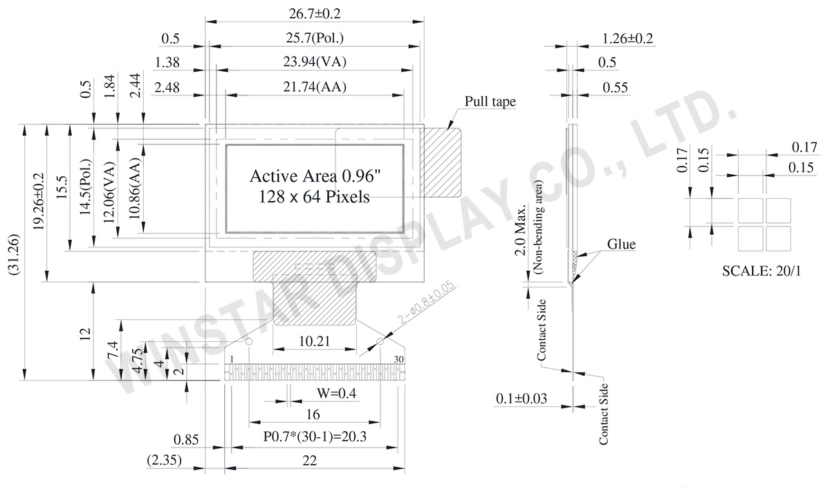
DESSIN
Data source ref:WEO012864ADWPP3N00000
SPÉCIFICATIONS
Spécifications générales
Article
Dimensions
Unité
Matrice de points
128 x 64 Dots
-
Dimensions du module
26.70 × 19.26 ×1.26
mm
Zone active
21.74 × 10.86
mm
Taille des points
0.15 × 0.15
mm
Pas des points
0.17 × 0.17
mm
Mode d'affichage
Matrice passive
Couleur d'affichage
Monochrome
Drive Duty
1/64 Duty
Controller IC
ST7315
Interface
6800, 8080, SPI, I2C
Diagonale
0.96 pouces
Valeurs nominales maximales absolues
Parameter
Symbole
Valeur min
Valeur max
Unité
Supply Voltage for Logic
VDD
-0.3
5.5
V
Supply Voltage for Display
VOLED
0
18.0
V
Température de fonctionnement
TOP
-40
+80
°C
Température de stockage
TSTG
-40
+85
°C
Caractéristiques électroniques
DC Caractéristiques électroniques
Article
Symbole
État
Valeur min
Valeur type
Valeur max
Unité
Supply Voltage for Logic
VDD
-
2.4
3.0
5.0
V
Supply Voltage for Display
(Supplied Externally)
VOLED
-
7.5
12.0
16.5
V
Charge Pump Regulator
Supply Voltage
VBAT
-
3.0
3.5
5.0
V
Charge Pump Output Voltage for Display (Generated by Internal DC/DC)
Charge Pump
VOLED
-
7.0
7.5
-
V
Input High Volt.
VIH
-
0.8×VDD
-
-
V
Input Low Volt.
VIL
-
-
-
0.2×VDD
V
Output High Volt.
VOH
-
0.9×VDD
-
-
V
Output Low Volt.
VOL
-
-
-
0.1×VDD
V
Display 50% Pixel on
Operating Current for VOLED
(VOLED Supplied Externally)
IOLED
VOLED=12V
-
6
12
mA
Display 50% Pixel on
(VOLED Generated by Internal DC/DC)
IBAT
VBAT=3.5V
-
15
30
mA
Fonction PIN sur l'interface
No.
Symbole
Fonction
1
N.C. (GND)
The supporting pins can reduce the influences from stresses on the function pins. These pins must be connected to external ground.
2
C2N
DC/DC voltage converter.
Connect a capacitor between CA1P and CA1N.
Connect a capacitor between CA2P and CA2N.
3
C2P
4
C1P
5
C1N
6
VBAT
Analog power for internal booster. If VDD=VABT
7
NC
NC
8
DGND
Digital ground. Connect to GND
9
VDD
Power supply pin for core logic operation.
10
IF0
These pins select interface operation mode.
IF2
IF1
IF0
MPU interface type
L
L
L
4-line serial interface
L
L
H
3-line serial interface
L
H
L
I2C serial interface
H
H
L
8-bit 8080 parallel interface
H
L
L
8-bit 6800 parallel interface
11
IF1
12
IF2
13
CSB
Chip select input pin.
CSB=“L”: This chip is selected and the MPU interface is active.
CSB=“H”: This chip is not selected and the MPU interface is disabled (D[7:0] are high impedance).
14
RSTB
This pin is reset signal input. When the pin is low, initialization of the chip is executed. Keep this pin HIGH (i.e. connect to VDD) during normal operation.
15
A0
It determines whether the access is related to data or command.
A0 = "H": Indicates that D[7:0] are display data;
A0 = "L": Indicates that D[7:0] are control data.
This pin is I2C slave address bit (SA0), when I2C interface is selected.
16
RWR
Read / Write execution control pin. (This pin is only used in parallel interface)
Write enable input pin.
The data are latched at the rising edge of th /WR signal.
This pin is not used in serial interfaces and should be connected to DGND.
17
ERD
Read / Write execution control pin. (This pin is only used in parallel interface)
MPU Type
ERD
Description
6800-series
ERD
Read / Write control input pin.
R/W = "H": When E is "H", data bus is in output status.
R/W = "L": The data are latched at the falling edge of the E signal.
8080-series
/RD
Read enable input pin.
When /RD is "L", data bus is in output status.
This pin is not used in serial interfaces and should be connected to DGND.
18~25
D0~D7
When using 8-bit parallel interface: 8080 or 6800 mode 8 bit bi-directional data bus. Connect to the data bus of 8-bit microprocessor. When CSB is “H”, D[7:0] are high impedance. When using serial interface : 3-line SPI or 4-line SPI mode
D[2:1] : serial input/output data (SDA).
D[0] : serial input clock (SCL).
D1 to D2 must be connected together (SDA)
D[7:3] : fix to “L” by DGND. When using serial interface : I2C interface
D[2] : SDA_OUT, serial data and acknowledge output for the I2C interface.
D[1] : SDA_IN, serial input data
D[0] : SCL, serial input clock .
D1 to D2 must be connected together (SDA)
D[7:3] : fix to “L” by DGND.
26
IREF
Internal IREF is used, please leave this pin open.
27
VCOMH
VCOMH is the driving voltage for common and segment circuits.
28
VOLED
VOLED is the diving voltage for segment circuit.
29
PGND
Analog ground. Connect to GND
30
NC
(GND)
The supporting pins can reduce the influences from stresses on the function pins. These pins must be connected to external ground.
En cliquant sur "Autoriser tous les cookies", vous acceptez le stockage de cookies sur votre appareil pour améliorer la navigation sur le site, analyser l'utilisation du site et aider dans nos efforts de marketing et de performance. Vous pouvez trouver plus d'informations à ce sujet dans notre politique. Politique de confidentialité