O modelo WEO012864AD é um display gráfico OLED de 0,96 polegadas com estrutura COG, oferecendo imagens claras com resolução de 128x64 pixels. Este tela OLED 0,96" é alimentado pelo IC ST7315 e suporta comunicação via I2C, paralelo 6800 ou 8080 e interfaces SPI de 3/4 linhas. O display opera com uma tensão de alimentação típica de 12V, com ciclo de condução de 1/64 e uma tensão de alimentação lógica de 3,0V (valor típico). Com a exibição em padrão xadrez a 50% (cor branca), o consumo de corrente é de 6mA @ 3,0VCC. O modelo WEO012864AD é uma solução IC alternativa ao modelo WEO012864D, com características elétricas e definições de pinos PFC idênticas, exigindo apenas pequenos ajustes no código inicial para garantir compatibilidade. Os módulos de display OLED 0,96" da WINSTAR estão disponíveis em várias opções, como o WEO012864C com o IC SH1106, o WEO012864AC com o IC SSD1315 e este WEO012864AD com o IC ST7315, oferecendo flexibilidade na escolha da solução ideal para suas aplicações.
Este módulo 128x64 OLED I2C é ideal para uso em dispositivos de automação residencial, sistemas POS financeiros, aplicativos Cloud/IoT, dispositivos tecnológicos inteligentes, sistemas de energia, sistemas de comunicação, instrumentos médicos e muito mais. Ele opera em uma ampla faixa de temperatura de -40℃ a +80℃ e tem uma faixa de temperatura de armazenamento de -40℃ a +85℃, tornando-o adequado para uma variedade de ambientes.
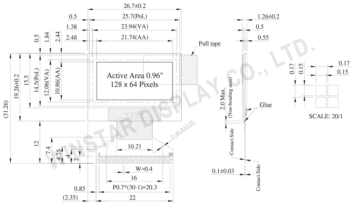
DRAWING
Data source ref:WEO012864ADWPP3N00000
SPECIFICATIONS
Dados Mecânicos
Item
Dimensão
Unidade
Matriz de pontos
128 x 64 Dots
-
Dimensão do módulo
26.70 × 19.26 ×1.26
mm
Área ativa
21.74 × 10.86
mm
Tamanho do ponto
0.15 × 0.15
mm
Distância entre pontos
0.17 × 0.17
mm
Modo de exibição
Passive Matrix
Cor de exibição
Monochrome
Drive Duty
1/64 Duty
Controller IC
ST7315
Interface
6800, 8080, SPI, I2C
Tamanho
0,96 polegadas
Classificações Máximas Absolutas
Parameter
Símbolo
Valor Min
Valor Máximo
Unidade
Supply Voltage for Logic
VDD
-0.3
5.5
V
Supply Voltage for Display
VOLED
0
18.0
V
Temperatura de operação
TOP
-40
+80
°C
Temperatura de armazenamento
TSTG
-40
+85
°C
Características Eletrônicas
DC Características Eletrônicas
Item
Símbolo
Condição
Valor Min
Valor Típico
Valor Máximo
Unidade
Supply Voltage for Logic
VDD
-
2.4
3.0
5.0
V
Supply Voltage for Display
(Supplied Externally)
VOLED
-
7.5
12.0
16.5
V
Charge Pump Regulator
Supply Voltage
VBAT
-
3.0
3.5
5.0
V
Charge Pump Output Voltage for Display (Generated by Internal DC/DC)
Charge Pump
VOLED
-
7.0
7.5
-
V
Input High Volt.
VIH
-
0.8×VDD
-
-
V
Input Low Volt.
VIL
-
-
-
0.2×VDD
V
Output High Volt.
VOH
-
0.9×VDD
-
-
V
Output Low Volt.
VOL
-
-
-
0.1×VDD
V
Display 50% Pixel on
Operating Current for VOLED
(VOLED Supplied Externally)
IOLED
VOLED=12V
-
6
12
mA
Display 50% Pixel on
(VOLED Generated by Internal DC/DC)
IBAT
VBAT=3.5V
-
15
30
mA
Função do pino de interface
No.
Símbolo
Função
1
N.C. (GND)
The supporting pins can reduce the influences from stresses on the function pins. These pins must be connected to external ground.
2
C2N
DC/DC voltage converter.
Connect a capacitor between CA1P and CA1N.
Connect a capacitor between CA2P and CA2N.
3
C2P
4
C1P
5
C1N
6
VBAT
Analog power for internal booster. If VDD=VABT
7
NC
NC
8
DGND
Digital ground. Connect to GND
9
VDD
Power supply pin for core logic operation.
10
IF0
These pins select interface operation mode.
IF2
IF1
IF0
MPU interface type
L
L
L
4-line serial interface
L
L
H
3-line serial interface
L
H
L
I2C serial interface
H
H
L
8-bit 8080 parallel interface
H
L
L
8-bit 6800 parallel interface
11
IF1
12
IF2
13
CSB
Chip select input pin.
CSB=“L”: This chip is selected and the MPU interface is active.
CSB=“H”: This chip is not selected and the MPU interface is disabled (D[7:0] are high impedance).
14
RSTB
This pin is reset signal input. When the pin is low, initialization of the chip is executed. Keep this pin HIGH (i.e. connect to VDD) during normal operation.
15
A0
It determines whether the access is related to data or command.
A0 = "H": Indicates that D[7:0] are display data;
A0 = "L": Indicates that D[7:0] are control data.
This pin is I2C slave address bit (SA0), when I2C interface is selected.
16
RWR
Read / Write execution control pin. (This pin is only used in parallel interface)
Write enable input pin.
The data are latched at the rising edge of th /WR signal.
This pin is not used in serial interfaces and should be connected to DGND.
17
ERD
Read / Write execution control pin. (This pin is only used in parallel interface)
MPU Type
ERD
Description
6800-series
ERD
Read / Write control input pin.
R/W = "H": When E is "H", data bus is in output status.
R/W = "L": The data are latched at the falling edge of the E signal.
8080-series
/RD
Read enable input pin.
When /RD is "L", data bus is in output status.
This pin is not used in serial interfaces and should be connected to DGND.
18~25
D0~D7
When using 8-bit parallel interface: 8080 or 6800 mode 8 bit bi-directional data bus. Connect to the data bus of 8-bit microprocessor. When CSB is “H”, D[7:0] are high impedance. When using serial interface : 3-line SPI or 4-line SPI mode
D[2:1] : serial input/output data (SDA).
D[0] : serial input clock (SCL).
D1 to D2 must be connected together (SDA)
D[7:3] : fix to “L” by DGND. When using serial interface : I2C interface
D[2] : SDA_OUT, serial data and acknowledge output for the I2C interface.
D[1] : SDA_IN, serial input data
D[0] : SCL, serial input clock .
D1 to D2 must be connected together (SDA)
D[7:3] : fix to “L” by DGND.
26
IREF
Internal IREF is used, please leave this pin open.
27
VCOMH
VCOMH is the driving voltage for common and segment circuits.
28
VOLED
VOLED is the diving voltage for segment circuit.
29
PGND
Analog ground. Connect to GND
30
NC
(GND)
The supporting pins can reduce the influences from stresses on the function pins. These pins must be connected to external ground.
Ao clicar em "Permitir todos os cookies", você concorda com o armazenamento de cookies no seu dispositivo para melhorar a navegação no site, analisar o uso do site e auxiliar nossos esforços de marketing e desempenho. Você pode encontrar mais informações sobre esse assunto em nossa política. Política de privacidade