Home Productos Pantalla OLED Pantalla OLED Gráfico WEO128128A

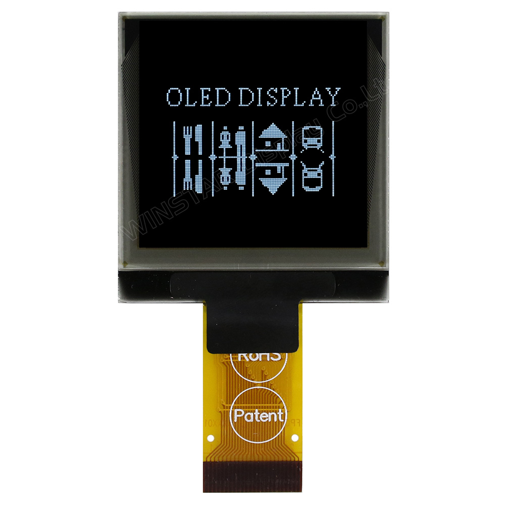
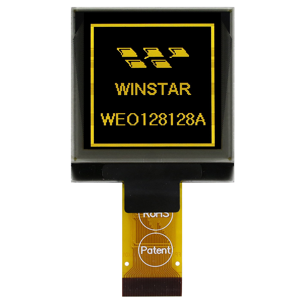
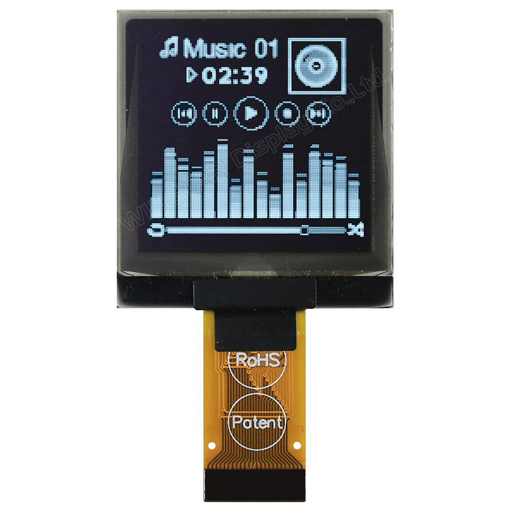
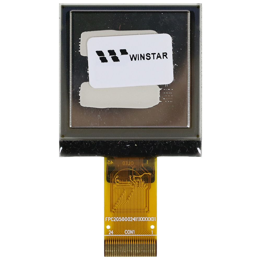
Pantalla OLED SSD1327 1.5 pulgada 128x128

Modelo Nº WEO128128A

►Tipo : Gráfico
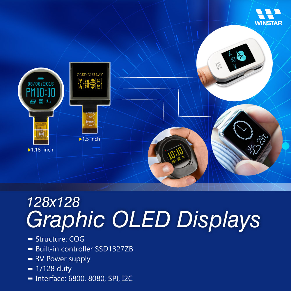
►Estructura : COG
►Tamaño: 1.5 pulgada
►Matriz de puntos 128x128
►IC:SSD1327
►Fuente de alimentación de 3V
►1/128 duty
►Interfaz : 6800, 8080, SPI, I2C
►Color de la pantalla: Blanco / Amarillo
►Compatibilidad con escala de grises
►Otras opciones de FPC disponibles en la siguiente tabla.

Descripción


   Opciones de FPC


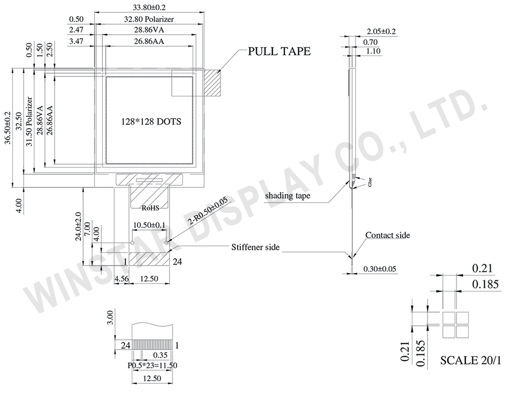
DIBUJO

OLED Display 128x128, 128x128 OLED Display, 128x128 pixel OLED Module - WEO128128A


Data source ref: WEO128128ALAP3N00000

ESPECIFICACIONES

Datos mecánicos

Elemento Valor estándar Unidad
Matriz de puntos 128 x 128 Dots
Dimensión del módulo 33.80 x 36.50 x 2.05 mm
zona activa 26.86 x 26.86 mm
Tamaño del punto 0.185 x 0.185 mm
Distancia entre puntos 0.210 x 0.210 mm
Modo de visualización Matriz Pasiva
Color de la pantalla Monocromos
Drive Duty 1/128 Duty
Escala de grises 4 bits
IC SSD1327
Interfaz 6800,8080,SPI,I2C
Tamaño 1.5 pulgada

Valores nominales máximos absolutos

Parameter Symbol Valor mín. Valor máx. Unidad
Low voltage power supply, power supply for I/O pins VCI -0.3 4.0 V
Supply Voltage for Logic VDD -0.5 2.75 V
Supply Voltage for Display VCC -0.5 19.0 V
Temperatura de funcionamiento TOP -40 +80 °C
Temperatura de almacenamiento TSTG -40 +85 °C

Características electrónicas

Elemento Symbol Condición Valor mín. Valor típico Valor máx. Unidad
Low voltage power supply, power supply for I/O pins VCI   2.8 3 3.3 V
Supply Voltage for Display VCC 14 14.5 15 V
Supply Voltage for Logic VDD 2.4 2.6 V
High Level Input VIH 0.8×VCI VCI V
Low Level Input VIL 0 0.2×VCI V
High Level Output VOH 0.9×VCI VCI V
Low Level Output VOL 0 0.1×VCI V
50% Check Board operating Current VCC =14.5V 24 36 mA

Función interfaz Pin

No. Símbolo Función
1 VSS Ground pin. It must be connected to external ground.
2 VCC Power supply for panel driving voltage. This is also the most positive power voltage supply pin. It is supplied by external high voltage source.
3 VCOMH COM signal deselected voltage level.
A capacitor should be connected between this pin and VSS. No external power supply is allowed to connect to this pin.
4 VCI Low voltage power supply and power supply for interface logic level. It should match with the MCU interface voltage level and must be connected to external source.
VCI must always set to be equivalent to or higher than VDD.
5 VDD Power supply pin for core logic operation.
VDD can be supplied externally (within the range of 2.4V to 2.6V) or regulated
Internally from VCI. A capacitor should be connected between VDD and VSS under all circumstances.
6 BS1 MCU bus interface selection pins. Select appropriate logic setting as described in the following table. BS2 and BS1 are pin select.
Bus Interface selection
BS[2:1] Interface
00 4 line SPI
01 I2C
11 8-bit 8080 parallel
10 8-bit 6800 parallel
Note  (1) 0 is connected to VSS  (2) 1 is connected to VCI
7 BS2
8 VSS Ground pin. It must be connected to external ground.
9 IREF This pin is the segment output current reference pin
10 CS# This pin is the chip select input connecting to the MCU.
The chip is enabled for MCU communication only when CS# is pulled LOW (active LOW).
11 RES# This pin is reset signal input.
When the pin is pulled LOW, initialization of the chip is executed.
Keep this pin pull HIGH during normal operation.
12 D/C This pin is Data/Command control pin connecting to the MCU.
When the pin is pulled HIGH, the data at D[7:0] will be interpreted as data.
When the pin is pulled LOW, the data at D[7:0] will be transferred to a command register.
In I2C mode, this pin acts as SA0 for slave address selection.
13 W/R# This pin is read / write control input pin connecting to the MCU interface.
When 6800 interface mode is selected, this pin will be used as Read/Write (R/W#) selection input. Read mode will be carried out when this pin is pulled HIGH and write mode when LOW.
When 8080 interface mode is selected, this pin will be the Write (WR#) input. Data write operation is initiated when this pin is pulled LOW and the chip is selected.

Opciones de FPC:

Dibujo FPC Length PIN Pitch ZIF FPC or HOTBAR FPC Interfaz FPC No. Create Date
FPC2050002411XXXXX03_WEO128128ALAP3N00000 25.05 24 0.5 ZIF 6800,8080,SPI,I2C FPC2050002411XXXXX03 20150901
FPC2050002411XXXXX12_WEO128128AWAP3N00002 41 24 0.5 ZIF 6800,8080,4-Wire SPI,I2C FPC2050002411XXXXX12 20200116

Productos relacionados

go top
close

Valoramos tu privacidad

Al hacer clic en "Permitir todas las cookies", aceptas el almacenamiento de cookies en tu dispositivo para mejorar la navegación en el sitio, analizar el uso del sitio y ayudar en nuestros esfuerzos de marketing y rendimiento. Puedes encontrar más información sobre este tema en nuestra política. Política de privacidad

Valoramos tu privacidad

Winstar y ciertos terceros utilizan cookies en www.winstar.com.tw. Los detalles sobre los tipos de cookies, su propósito y las partes involucradas se describen a continuación y en nuestra Política de Cookies. Haga clic en “Permitir todos” para dar su consentimiento para el uso de cookies y tener la mejor experiencia posible en nuestros sitios web. También puede establecer sus preferencias o rechazar cookies (excepto las cookies estrictamente necesarias).

Gestionar preferencias de consentimiento

Siempre activo
Cookies esenciales

Estas cookies son esenciales para permitirte navegar por el sitio web y utilizar sus funciones, como establecer tus preferencias de privacidad, iniciar sesión o completar formularios.

Cookies de análisis

También conocidos como "cookies estadísticas", estas cookies recogen información sobre cómo utilizas un sitio web, como qué páginas has visitado y qué enlaces has clicado. Ver detalles.