 - WEO012864J")

我们重视您的隐私
通过点击「允许所有 Cookie」,代表您同意在您的设备上存储 Cookie 以增强网站浏览体验、分析网站使用情况并协助我们的营销和网站效能优化工作。您可以在我们的隐私权政策中找到有关于此的更多信息。


2.42寸是市场上热门的显示器尺寸,华凌推出 WEO012864J-CTP 2.4寸绘图型OLED显示模块搭配电容式触控面板产品,模块分辨率为128x64、内建SSD1309 IC、预设6800 8-bit并列接口,可选择8080并列接口、4-线SPI或I2C接口,支持逻辑电源电压3V、 驱动方式1/64。 WEO012864J-CTP模块的触控面板,内建GT911 IC,使用I2C接口、支持1指触控。
模块上设计铁框和PCB板客户不需要额外自行开发PCB,而PCB上四个螺丝孔让客户安装更加便利。此款2.42寸OLED显示器搭载PCAP电容式触控面板非常适合应用于智能家电、智能技术设备、仪表设备、通信系统、医疗仪器设备...等。此OLED型号具有10,000:1的高对比度度,让影像显示更清晰,模块可在-20℃至+70℃温度下工作,储存温度-30℃至+80℃。
| 项目 | 规格 | 单位 |
|---|---|---|
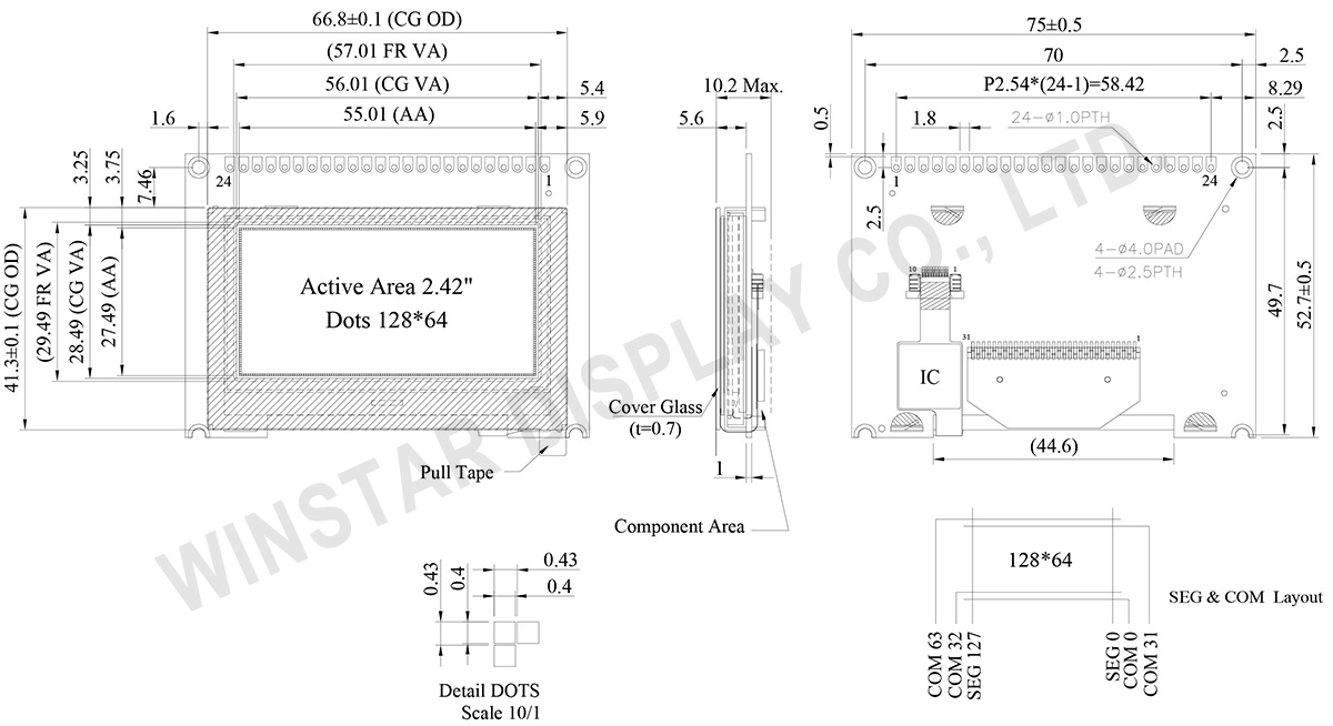
| 点阵(分辨率) | 128 x 64 | - |
| 模块尺寸 | 75.0 × 52.7 ×10.2 MAX | mm |
| 有效区域 | 55.01 × 27.49 | mm |
| 点大小 | 0.40 × 0.40 | mm |
| 点间距 | 0.43 × 0.43 | mm |
| 显示模式 | 被动矩阵 | |
| 发光颜色 | 单色 | |
| 驱动方式 | 1/64 Duty | |
| IC | SSD1309 | |
| 接口 | 预设8Bits 6800, 可选 8080 / 4-SPI / I2C | |
| 尺寸 | 2.42 寸 | |
| PCAP IC | GT911 | |
| Detect Point | 1 | |
| PCAP 接口 | I2C | |
| 表面 | 亮面 | |
| 参数 | 符号 | 最小值 | 最大值 | 单位 |
|---|---|---|---|---|
| 逻辑电源电压 | VDD | -0.3 | 4 | V |
| 工作温度 | TOP | -20 | +70 | °C |
| 储存温度 | TSTG | -30 | +80 | °C |
| 项目 | 符号 | 条件 | 最小值 | 典型值 | 最大值 | 单位 |
|---|---|---|---|---|---|---|
| 逻辑电源电压 | VDD | - | 2.8 | 3.0 | 3.3 | V |
| 输入高准位 | VIH | - | 0.8×VDD | - | - | V |
| 输入低准位 | VIL | - | - | - | 0.2×VDD | V |
| 输出高准位 | VOH | - | 0.9×VDD | - | - | V |
| 输出低准位 | VOL | - | - | - | 0.1×VDD | V |
| 50%显示画面耗电流 | IDD | VDD =3V | - | 150 | 300 | mA |
| No. | 符号 | 说明 |
|---|---|---|
| 1 | VDD | Power supply pin for core logic operation |
| 2 | VSS | Ground. |
| 3 | NC(GND) | No connection |
| 4~11 | D0~D7 | These pins are bi-directional data bus connecting to the MCU data bus. Unused pins are recommended to tie LOW. |
| 12 | CS# | This pin is the chip select input connecting to the MCU. The chip is enabled for MCU communication only when CS# is pulled LOW (active LOW). |
| 13 | NC(GND) | No connection |
| 14 | RES# | This pin is reset signal input. When the pin is pulled LOW, initialization of the chip is executed. Keep this pin pull HIGH during normal operation. |
| 15 | R/W# | This pin is read / write control input pin connecting to the MCU interface. When 6800 interface mode is selected, this pin will be used as Read/Write (R/W#) selection input. Read mode will be carried out when this pin is pulled HIGH and write mode when LOW. |
| 16 | D/C# | This pin is Data/Command control pin connecting to the MCU. When the pin is pulled HIGH, the data at D[7:0] will be interpreted as data. When the pin is pulled LOW, the data at D[7:0] will be transferred to a command register. |
| 17 | E | This pin is MCU interface input. When 6800 interface mode is selected, this pin will be used as the Enable (E) signal. |
| 18 | NC(GND) | No connection |
| 19 | DISP | No Connection |
| 20 | NC(GND) | No connection |
| 21 | TP_INT | Interrupt signal, active low, asserted to request Host start a new transaction |
| 22 | TP_SDA | I2C data signal |
| 23 | TP_SCL | I2C clock signal |
| 24 | TP_RST | External reset signal, active low |

通过点击「允许所有 Cookie」,代表您同意在您的设备上存储 Cookie 以增强网站浏览体验、分析网站使用情况并协助我们的营销和网站效能优化工作。您可以在我们的隐私权政策中找到有关于此的更多信息。