

私たちはあなたのプライバシーを大切にします
「すべてのクッキーを許可」をクリックすると、サイトのナビゲーションを向上させ、サイト使用状況を分析し、マーケティングおよびパフォーマンスの取り組みを支援するために、クッキーをデバイスに保存することに同意したことになります。この件に関する詳細情報は、ポリシーをご覧ください。プライバシーポリシー

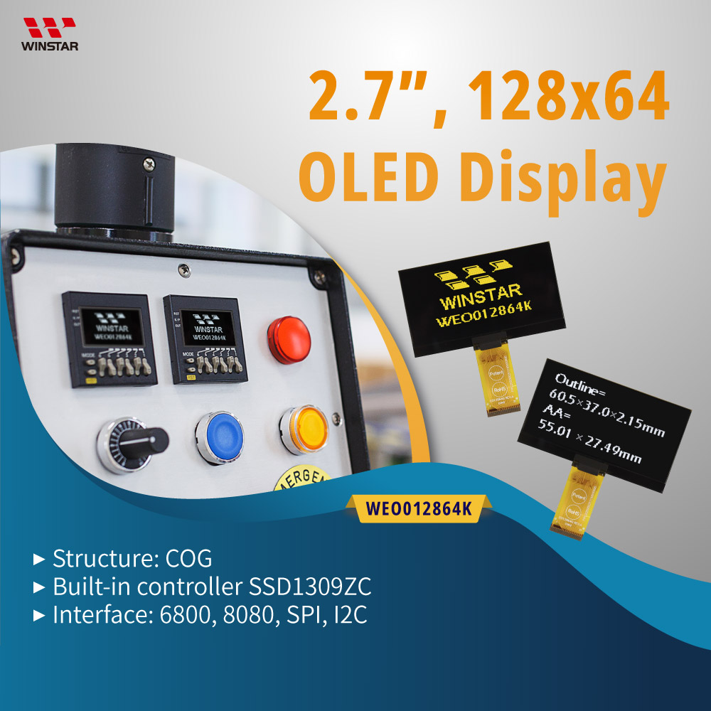
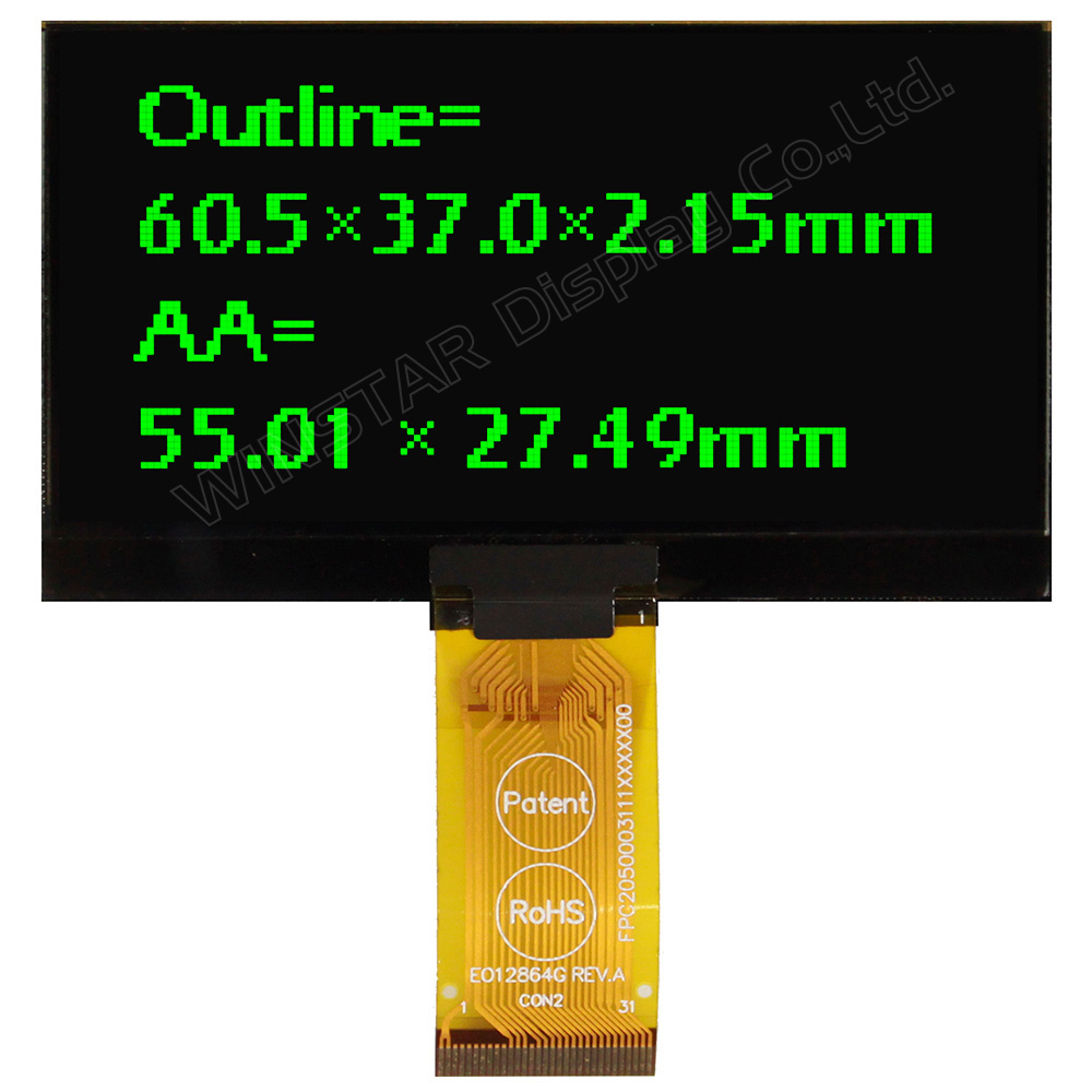
型番 WEO012864K
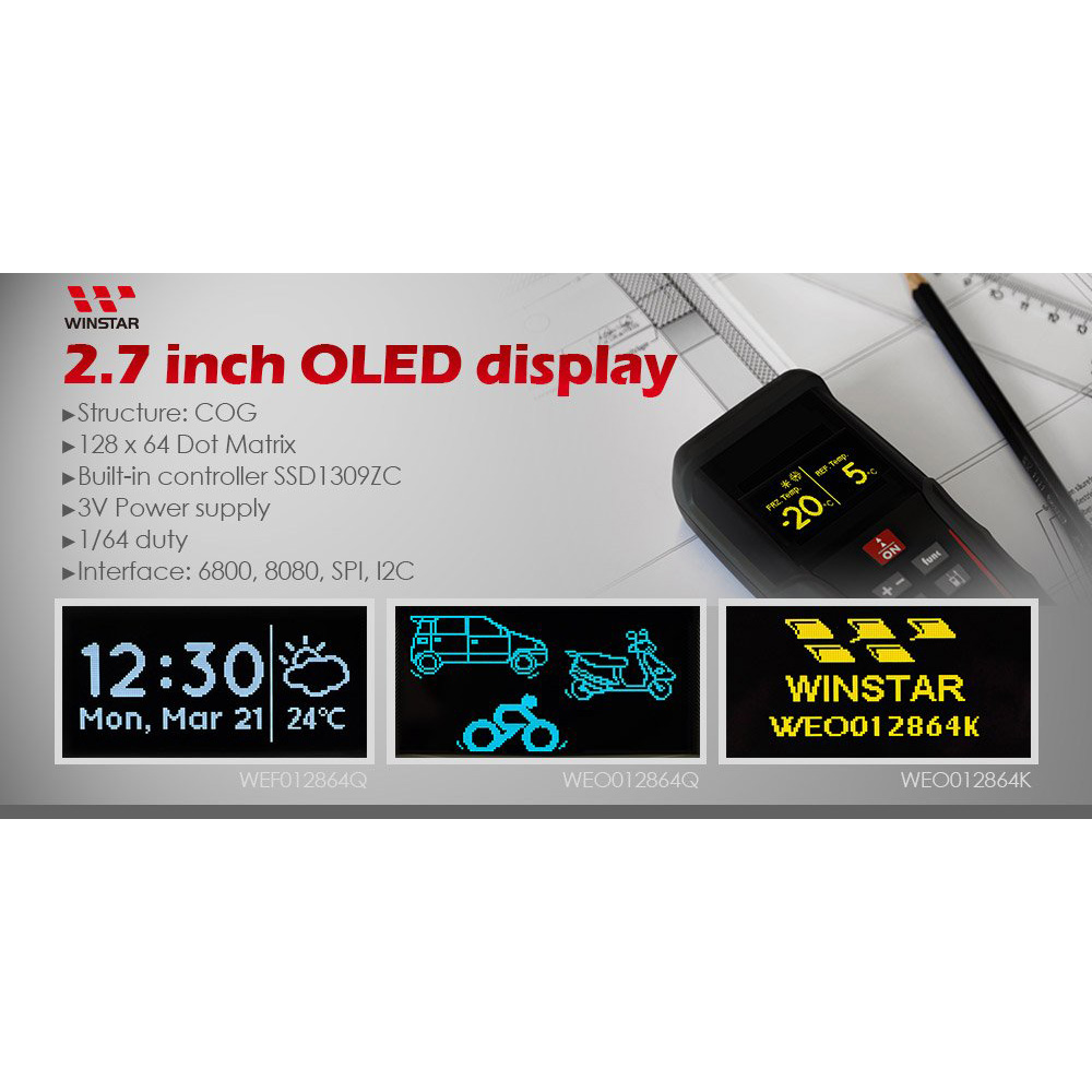
►タイプ: グラフィック有機EL液晶
►結構: COG; Frame Option
►サイズ: 2.7インチ
►128 x 64 ドットマトリックス
►IC:SSD1309
►3V電源電圧
►1/64 duty
►インターフェース: 6800, 8080, SPI, I2C
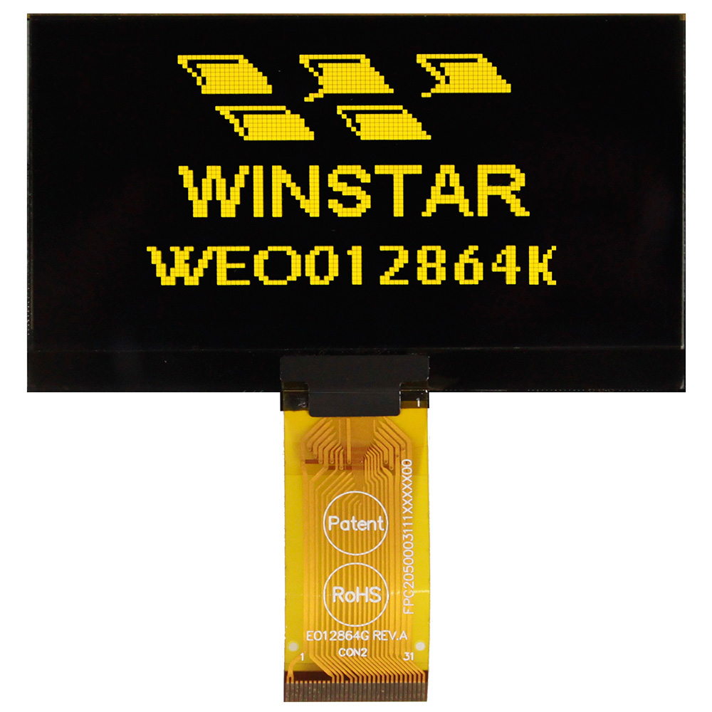
►発光色: 白色 / 黄色 / 空色 / 緑色
►Other FPC options available in below table
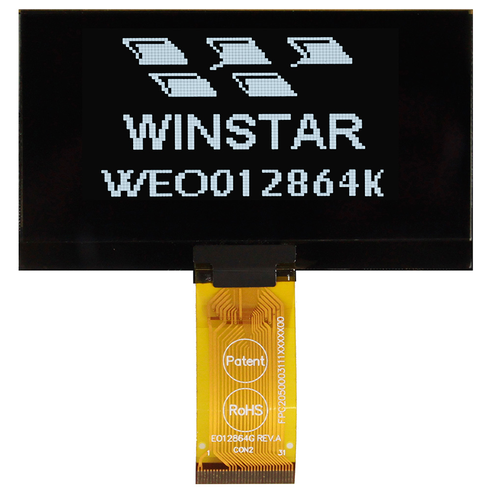
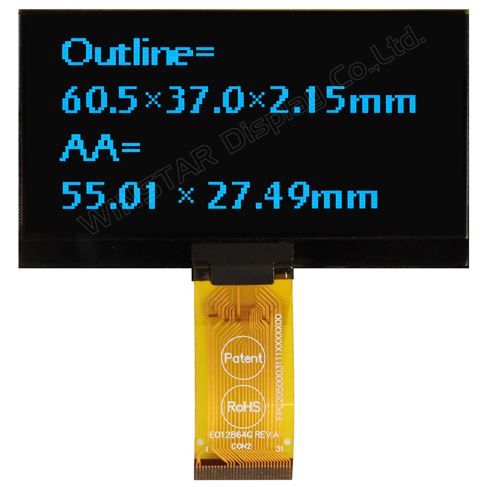
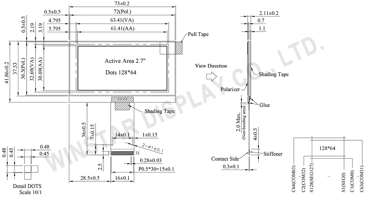
WEO012864Kは、128x64ドットの解像度を備えた2.7インチのモノクログラフィックOLEDディスプレイです。Chip-on-Glass(COG)構造を採用し、モジュール外形寸法は73.0 × 41.86 × 2.11 mm、有効表示領域は61.41 × 30.69 mmです。薄型のCOG構造により、組み込み時の厚みを抑えられるため、設置スペースに制約のある機器設計に適しています。
本グラフィックOLEDモジュールは、SSD1309コントローラICを搭載し、6800/8080パラレルインターフェース、SPI、I2Cに対応しています。ホストシステムのインターフェース要件に応じた接続が可能です。ロジック電源電圧(VDD)は2.8~3.3V(標準3.0V)、表示駆動電圧(VCC)は12~14V(標準13V)です。駆動方式は1/64 Dutyで、表示色は白、黄、スカイブルー、緑の単色仕様から選択できます。
WEO012864Kには、ケーブル長やピン数の異なる複数のFPC仕様が用意されており、PCBレイアウトや接続条件に応じて選択できます。また、WEF012864Kシリーズでは、SUS-304ステンレス製フレーム付き仕様も選択可能です。これらの構成オプションにより、産業機器、組み込みシステム、ローカル監視インターフェースなどへの組み込みに柔軟に対応できます。
サーバー機器へのOLEDディスプレイの組み込みや活用については、技術記事「2Uサーバーのローカル監視インターフェースにおけるPMOLEDの活用と設計」をご参照ください。
| 項目 | 仕様 | 単位 |
|---|---|---|
| ドットマトリックス(解像度) | 128 x 64 | - |
| モジュールサイズ | 73.0 × 41.86 × 2.11 | mm |
| 有効エリア | 61.41 × 30.69 | mm |
| ドットサイズ | 0.45 × 0.45 | mm |
| ドットピッチ | 0.48 × 0.48 | mm |
| 表示モード | パッシブマトリックス | |
| 発光色 | モノクロ | |
| 駆動方法 | 1/64 Duty | |
| パラメーター | 記号 | 最小値 | 最大値 | 単位 |
|---|---|---|---|---|
| ロジック電源電圧 | VDD | -0.3 | 4 | V |
| Display電源電圧 | VCC | 0 | 15 | V |
| 操作温度 | TOP | -40 | +80 | °C |
| 保存温度 | TSTG | -40 | +85 | °C |
| 項目 | 記号 | 条件 | 最小値 | 典型値 | 最大値 | 単位 |
|---|---|---|---|---|---|---|
| ロジック電源電圧 | VDD | - | 2.8 | 3.0 | 3.3 | V |
| Display電源電圧 | VCC | - | 12 | 13 | 14 | V |
| 高レベル入力 | VIH | - | 0.8×VDD | - | - | V |
| 低レベル入力 | VIL | - | - | - | 0.2×VDD | V |
| 高レベル出力 | VOH | - | 0.9×VDD | - | - | V |
| 低レベル出力 | VOL | - | - | - | 0.1×VDD | V |
| 50% Check Board operating Current | VCC =13.0V | - | 22 | 33 | mA | |
| No. | 記号 | 説明 | |||||||||||||||
|---|---|---|---|---|---|---|---|---|---|---|---|---|---|---|---|---|---|
| 1 | NC(GND) | No connection | |||||||||||||||
| 2 | VSS | Ground. | |||||||||||||||
| 3-10 | NC | No connection | |||||||||||||||
| 11 | VDD | Power supply pin for core logic operation | |||||||||||||||
| 12 | BS1 | MCU bus interface selection pins. Select appropriate logic setting as described in the following table. BS2, BS1 and BS0 are pin select
(1) 0 is connected to VSS (2) 1 is connected to VDD |
|||||||||||||||
| 13 | BS2 | ||||||||||||||||
| 14 | NC | No connection | |||||||||||||||
| 15 | CS# | This pin is the chip select input connecting to the MCU. The chip is enabled for MCU communication only when CS# is pulled LOW (active LOW). |
|||||||||||||||
| 16 | RES# | This pin is reset signal input. When the pin is pulled LOW, initialization of the chip is executed. Keep this pin pull HIGH during normal operation. |
|||||||||||||||
| 17 | D/C# | This pin is Data/Command control pin connecting to the MCU. When the pin is pulled HIGH, the data at D[7:0] will be interpreted as data. When the pin is pulled LOW, the data at D[7:0] will be transferred to a command register. In I2C mode, this pin acts as SA0 for slave address selection. When 3-wire serial interface is selected, this pin must be connected to VSS. |
|||||||||||||||
| 18 | R/W# | This pin is read / write control input pin connecting to the MCU interface. When 6800 interface mode is selected, this pin will be used as Read/Write (R/W#) selection input. Read mode will be carried out when this pin is pulled HIGH and write mode when LOW. When 8080 interface mode is selected, this pin will be the Write (WR#) input. Data write operation is initiated when this pin is pulled LOW and the chip is selected. When serial or I2C interface is selected, this pin must be connected to VSS. |
|||||||||||||||
| 19 | E/RD# | This pin is MCU interface input. When 6800 interface mode is selected, this pin will be used as the Enable (E) signal. Read/write operation is initiated when this pin is pulled HIGH and the chip is selected. When 8080 interface mode is selected, this pin receives the Read (RD#) signal. Read operation is initiated when this pin is pulled LOW and the chip is selected. When serial or I2C interface is selected, this pin must be connected to VSS. |
|||||||||||||||
| 20~27 | D0~D7 | These pins are bi-directional data bus connecting to the MCU data bus. Unused pins are recommended to tie LOW. When serial interface mode is selected, D0 will be the serial clock input: SCLK; D1 will be the serial data input: SDIN and D2 should be kept NC. When I2C mode is selected, D2, D1 should be tied together and serve as SDAout, SDAin in application and D0 is the serial clock input, SCL. |
|||||||||||||||
| 28 | IREF | This pin is the segment output current reference pin. IREF is supplied externally. |
|||||||||||||||
| 29 | VCOMH | COM signal deselected voltage level. A capacitor should be connected between this pin and VSS. |
|||||||||||||||
| 30 | VCC | Power supply for panel driving voltage. This is also the most positive power voltage supply pin. | |||||||||||||||
| 31 | NC(GND) | No connection |
| Drawing | Material | FR No. | Detailed Drawing | Create Date |
|---|---|---|---|---|
 |
SUS-304 | FFL60128640A221XXX00 | View | 20120131 |
| Drawing | FPC Length | PIN | pitch | ZIF FPC or HOTBAR FPC | Interface | FPC No. | Create Date |
|---|---|---|---|---|---|---|---|
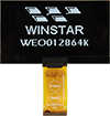 |
37 | 31 | 0.5 | ZIF | 6800, 8080, SPI, I2C | FPC2050003111XXXXX01 | 20140923 |
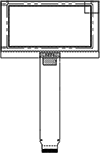 |
70.85 | 22 | 0.5 | ZIF | 6800, 8080, SPI, I2C | FPC2050002211XXXXX03 | 20161207 |
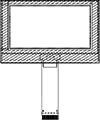 |
106.57 | 30 | 0.5 | ZIF | 6800, 8080, SPI, I2C | FPC2050003011XXXXX11 | 20170406 |
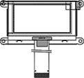 |
43.05 | 24 | 0.5 | ZIF | 6800, 8080, SPI, I2C | FPC2050002411XXXXX11 | 20191218 |


「すべてのクッキーを許可」をクリックすると、サイトのナビゲーションを向上させ、サイト使用状況を分析し、マーケティングおよびパフォーマンスの取り組みを支援するために、クッキーをデバイスに保存することに同意したことになります。この件に関する詳細情報は、ポリシーをご覧ください。プライバシーポリシー