

우리는 귀하의 프라이버시를 소중히 여깁니다
"모든 쿠키 허용"을 클릭하면 사이트 탐색을 개선하고, 사이트 사용을 분석하며, 마케팅 및 성능 노력에 도움을 주기 위해 쿠키를 귀하의 장치에 저장하는 데 동의한 것으로 간주됩니다. 이 주제에 대한 추가 정보는 당사의 정책에서 확인할 수 있습니다. 개인정보 보호정책

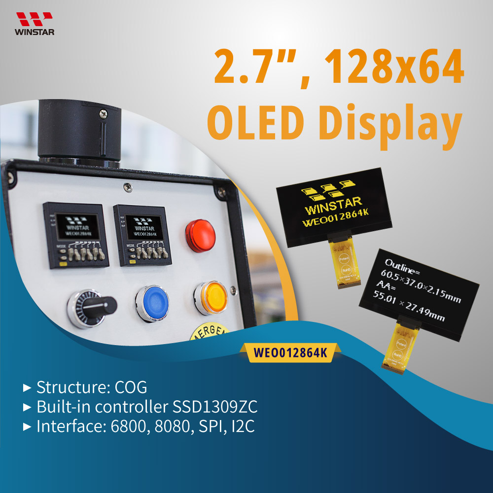
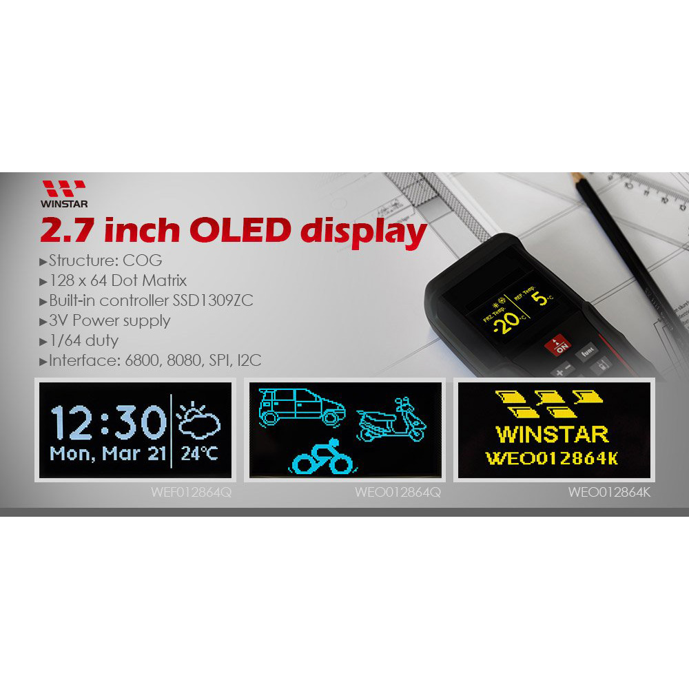
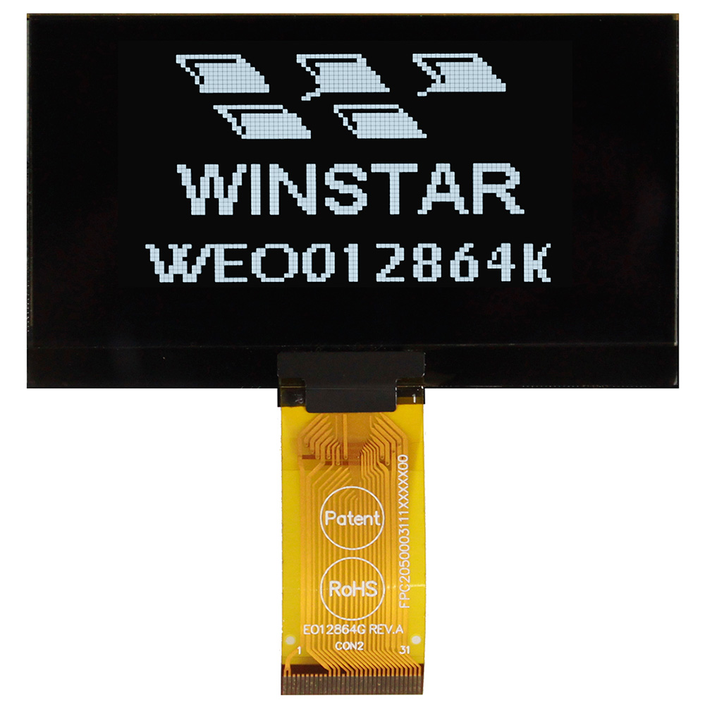
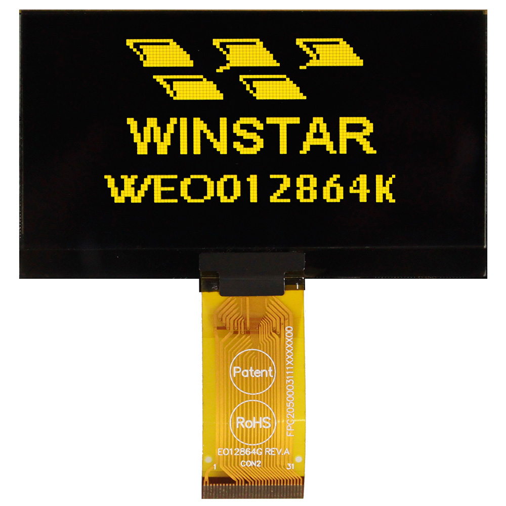
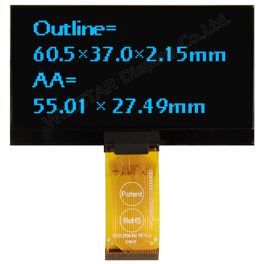
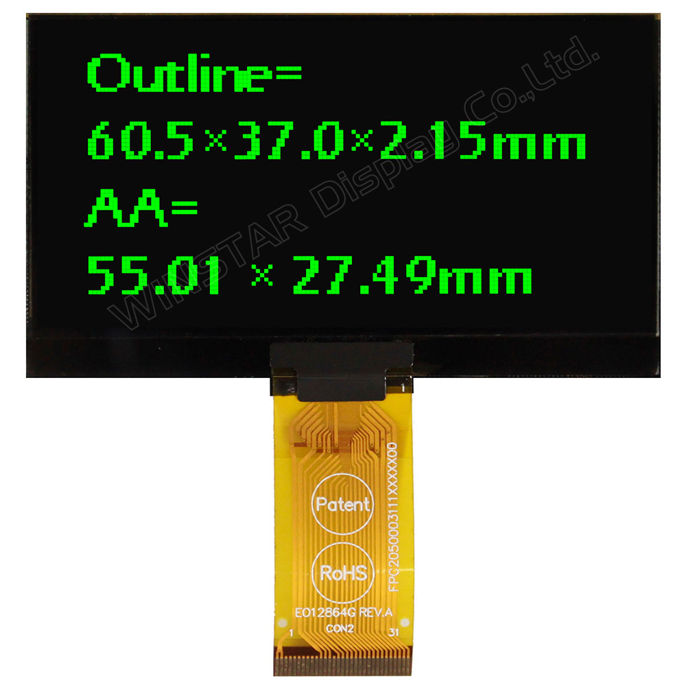
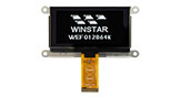
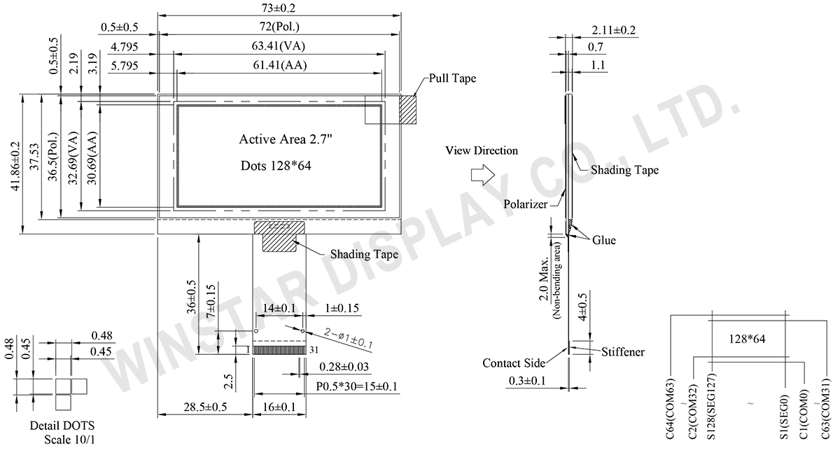
WEO012864K는 128x64 해상도를 지원하는 2.7인치 단색 그래픽 OLED 디스플레이로, Chip-on-Glass(COG) 구조를 적용한 제품입니다. 모듈 외형 치수는 73.0 × 41.86 × 2.11 mm이며, 유효 표시 영역은 61.41 × 30.69 mm입니다. 얇은 COG 구조로 모듈의 장착 두께를 줄일 수 있어 설치 공간이 제한된 장비 설계에 적합합니다.
이 그래픽 OLED 모듈에는 SSD1309 컨트롤러 IC가 내장되어 있으며, 6800/8080 병렬 인터페이스, SPI 및 I2C를 지원하여 다양한 호스트 시스템에 연결할 수 있습니다. 로직 전원 전압(VDD)은 2.8~3.3V(일반값 3.0V), 디스플레이 구동 전압(VCC)은 12~14V(일반값 13V)입니다. 1/64 Duty 구동 방식을 사용하며, 표시 색상은 흰색, 노란색, 하늘색, 녹색의 단색 옵션으로 제공됩니다.
WEO012864K는 케이블 길이와 핀 수가 서로 다른 다양한 FPC 구성 옵션을 제공하여 PCB 레이아웃과 연결 요구 사항에 따라 선택할 수 있습니다. 또한 WEF012864K 시리즈에는 SUS-304 스테인리스 스틸 프레임 옵션이 제공됩니다. 이러한 구성 옵션을 통해 산업용 장비, 임베디드 시스템 및 로컬 모니터링 인터페이스 등에 유연하게 통합할 수 있습니다.
서버 장비에 OLED 디스플레이를 적용하고 통합하는 방법에 대한 자세한 내용은 기술 자료 2U 서버 로컬 모니터링 인터페이스용 PMOLED 디스플레이의 적용 및 설계 시 고려사항을 참조하시기 바랍니다.
| 항목 | 치수 | 단위 |
|---|---|---|
| 도트 매트릭스 | 128 x 64 | - |
| 모듈 치수 | 73.0 × 41.86 × 2.11 | mm |
| 활성 영역 | 61.41 × 30.69 | mm |
| 도트 크기 | 0.45 × 0.45 | mm |
| 도트 피치 | 0.48 × 0.48 | mm |
| 디스플레이 모드 | 패시브 매트릭스 (Passive Matrix) | |
| 디스플레이 색 | Monochrome | |
| Drive Duty | 1/64 Duty | |
| Parameter | 기호 | 최소값 | 최대값 | 단위 |
|---|---|---|---|---|
| Supply Voltage for Logic | VDD | -0.3 | 4 | V |
| Supply Voltage for Display | VCC | 0 | 15 | V |
| 작동 온도 | TOP | -40 | +80 | °C |
| 보관 온도 | TSTG | -40 | +85 | °C |
| 항목 | 기호 | 조건 | 최소값 | 대표값 | 최대값 | 단위 |
|---|---|---|---|---|---|---|
| Supply Voltage for Logic | VDD | - | 2.8 | 3.0 | 3.3 | V |
| Supply Voltage for Display | VCC | - | 12 | 13 | 14 | V |
| High Level Input | VIH | - | 0.8×VDD | - | - | V |
| Low Level Input | VIL | - | - | - | 0.2×VDD | V |
| High Level Output | VOH | - | 0.9×VDD | - | - | V |
| Low Level Output | VOL | - | - | - | 0.1×VDD | V |
| 50% Check Board operating Current | VCC =13.0V | - | 22 | 33 | mA | |
| No. | 기호 | 기능 | |||||||||||||||
|---|---|---|---|---|---|---|---|---|---|---|---|---|---|---|---|---|---|
| 1 | NC(GND) | No connection | |||||||||||||||
| 2 | VSS | Ground. | |||||||||||||||
| 3-10 | NC | No connection | |||||||||||||||
| 11 | VDD | Power supply pin for core logic operation | |||||||||||||||
| 12 | BS1 | MCU bus interface selection pins. Select appropriate logic setting as described in the following table. BS2, BS1 and BS0 are pin select
(1) 0 is connected to VSS (2) 1 is connected to VDD |
|||||||||||||||
| 13 | BS2 | ||||||||||||||||
| 14 | NC | No connection | |||||||||||||||
| 15 | CS# | This pin is the chip select input connecting to the MCU. The chip is enabled for MCU communication only when CS# is pulled LOW (active LOW). |
|||||||||||||||
| 16 | RES# | This pin is reset signal input. When the pin is pulled LOW, initialization of the chip is executed. Keep this pin pull HIGH during normal operation. |
|||||||||||||||
| 17 | D/C# | This pin is Data/Command control pin connecting to the MCU. When the pin is pulled HIGH, the data at D[7:0] will be interpreted as data. When the pin is pulled LOW, the data at D[7:0] will be transferred to a command register. In I2C mode, this pin acts as SA0 for slave address selection. When 3-wire serial interface is selected, this pin must be connected to VSS. |
|||||||||||||||
| 18 | R/W# | This pin is read / write control input pin connecting to the MCU interface. When 6800 interface mode is selected, this pin will be used as Read/Write (R/W#) selection input. Read mode will be carried out when this pin is pulled HIGH and write mode when LOW. When 8080 interface mode is selected, this pin will be the Write (WR#) input. Data write operation is initiated when this pin is pulled LOW and the chip is selected. When serial or I2C interface is selected, this pin must be connected to VSS. |
|||||||||||||||
| 19 | E/RD# | This pin is MCU interface input. When 6800 interface mode is selected, this pin will be used as the Enable (E) signal. Read/write operation is initiated when this pin is pulled HIGH and the chip is selected. When 8080 interface mode is selected, this pin receives the Read (RD#) signal. Read operation is initiated when this pin is pulled LOW and the chip is selected. When serial or I2C interface is selected, this pin must be connected to VSS. |
|||||||||||||||
| 20~27 | D0~D7 | These pins are bi-directional data bus connecting to the MCU data bus. Unused pins are recommended to tie LOW. When serial interface mode is selected, D0 will be the serial clock input: SCLK; D1 will be the serial data input: SDIN and D2 should be kept NC. When I2C mode is selected, D2, D1 should be tied together and serve as SDAout, SDAin in application and D0 is the serial clock input, SCL. |
|||||||||||||||
| 28 | IREF | This pin is the segment output current reference pin. IREF is supplied externally. |
|||||||||||||||
| 29 | VCOMH | COM signal deselected voltage level. A capacitor should be connected between this pin and VSS. |
|||||||||||||||
| 30 | VCC | Power supply for panel driving voltage. This is also the most positive power voltage supply pin. | |||||||||||||||
| 31 | NC(GND) | No connection |
| 그림 | Material | FR No. | Detailed Drawing | Create Date |
|---|---|---|---|---|
 |
SUS-304 | FFL60128640A221XXX00 | View | 20120131 |
| 그림 | FPC Length | PIN | pitch | ZIF FPC or HOTBAR FPC | 인터페이스 | FPC No. | Create Date |
|---|---|---|---|---|---|---|---|
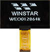 |
37 | 31 | 0.5 | ZIF | 6800, 8080, SPI, I2C | FPC2050003111XXXXX01 | 20140923 |
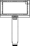 |
70.85 | 22 | 0.5 | ZIF | 6800, 8080, SPI, I2C | FPC2050002211XXXXX03 | 20161207 |
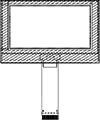 |
106.57 | 30 | 0.5 | ZIF | 6800, 8080, SPI, I2C | FPC2050003011XXXXX11 | 20170406 |
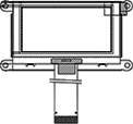 |
43.05 | 24 | 0.5 | ZIF | 6800, 8080, SPI, I2C | FPC2050002411XXXXX11 | 20191218 |


"모든 쿠키 허용"을 클릭하면 사이트 탐색을 개선하고, 사이트 사용을 분석하며, 마케팅 및 성능 노력에 도움을 주기 위해 쿠키를 귀하의 장치에 저장하는 데 동의한 것으로 간주됩니다. 이 주제에 대한 추가 정보는 당사의 정책에서 확인할 수 있습니다. 개인정보 보호정책